Discuss Cat 5 confusion as to which way in the Electrician Courses : Electrical Quals area at ElectriciansForums.net

Wilson12

-
Trainee
Reaction score
3
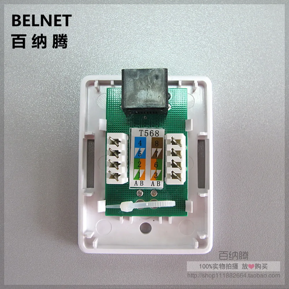
Something soo simple... cat 5 I’m heading into my am2 exam next week having never terminated the cable. I’ve searched online and I see different configurations everywhere
I’m confused as the numbers don’t line up with the colours the bottom diagram to the table also I’ve seen pictures of the faceplates and they have different colours inside.im unsure which way up also :/
Any help will be greatly appreciated
 
It may help to see this, this is the layout for making ends off on patch leads, in other words the order the pins are on the plug which plugs into the RJ45 socket you are wiring.
ethernet-cable-wiring-diagram-uk-fresh-cat-5-of-for-rj45-cable-wiring-diagram.jpg
 
Last edited:
View attachment 44474 Why is it different colours on the face plate to the colours in the drawing to the colours in the writing

There's different methods of wiring these up depending on what you plan on plugging into each end. For a normal patch lead you would want them to both be the same at each end. Option B (orange in 1 and so on) is usually the preferred way.

New modules are marked A & B, the one in your picture probably were at some point before it was reused a thousand times!
 
I’ve searched the internet and videos and all configurations are different.does different brands have different connections or something it’s not harmonised as long as it’s the same on the other end ?

In the diagram it shows
Top of socket

1. Green Blue
2. Green/white Blue/white
3.orange Brown
4.orane/white Brown/white

This is how I’m interpreting it am I wrong
 
Different layouts from different manufactures just like anything else. The colours and numbering stays the same though.
 
As @Resu said, there are two schemes typically in use for Category 5+ cabling. These are T568A and T568B. Nearly every installation I've ever seen/worked on has used T568B.

The only difference between the two is which pins orange, orange/white, green, green/white are assigned to.

But I think your confusion is arising because the diagram you have of the socket (and colours) does not match the physical socket you have.

Disregard the diagram and use the colours on the back of the physical socket. If you look carefully you'll see the punch down points on the left hand side are those which vary for T568A and T568B. They each have a colour blob next to them which is split in half. Look between the four punch down points and you'll see AB. The colours on the left hand side of each blob is the colour to use in that slot for T568A and on the right hand side, T568B.

Don't worry about the purpose of the cores or anything else. Providing you match the colours and use the same scheme at each end, the cable will be fine.

Looking at the photo of the module, you've got the oranges in the right place. The green... not so much as that looks like the green/white which should be in the bottom slot on the left.

Once you've done a few hundred, it will become second nature :D

Good luck
 
I feel like I should follow the diagram provided though as the back of the socket it’s missing some scratched off and we’ve been provided with the diagram ?
 
View attachment 44474 Why is it different colours on the face plate to the colours in the drawing to the colours in the writing

From this photo....

Orange to the top left
Orange white to the next one down
Green to the next one down
Green white to the bottom one

Ignore the table because it does not correspond to the physical kit you have. The fact they have given you a table showing T568B, use the wiring I've just given you and you will comply with T568B.

Based on that explanation... what colours are you going to use for the right hand side?

The table and diagram don't match the physical socket because the table is from one manufacturer and the socket is from another. This is why sockets and patch panels have clear colours on them (which are still present and clearly visible on the physical socket you have).
 
Looks like green is at the top left? They just give that diagram to follow soo it must be green top left?

I'm going to try this once more....

Ignore the diagram/table because it does not match the physical connector you have.

Use the colours printed on the back of the connector next to the termination points (these are clearly visible in the photo of the connector you posted) that correspond with B (also clearly visible in the photo).
 
Some more info (which may or may not make it clearer)

An RJ45 plug has 8 pins in a line.

These are numbered from 1 to 8 in order, and are always the same for every manufacturer. (With the clip on the bottom and the cable exiting towards you, pin one is on the left)

The socket also has 8 contacts in a row for the 8 pins, again in the same order for eveey manufacturer. But different manucaturers arange the punch down terminals (where you slot the cable) in different positions on the back. For this reason, they have the pin numbers and coresponding colours next to each punch down terminal.

To make it more confusing, there are 2 standards: T - 568A and T - 568B (often refered to as just A and B. T - 568B is almost always used so if in doubt, always go for the colours marked next to B.

So for T - 568 B
1 is always Orange/White
2 is always Orange
3 is always Green/White
4 is always Blue
5 is always Blue/White
6 is always Green
7 is always Brown/White
8 is always Brown

Just look on the back for which number relates to each terminal.

It is important to get the sequence right because the data is transmited down 4 twisted pairs (can be one Tx and one Rx, can be two Tx and Two Rx pairs depending on standard used). Its important that each pair are twisted together and not mixed up.

(I know most of this information has already been covered but ive tried to put it all together in a logical order)
 
I’ve got photos saved favourite on my phone and whether making up plug ends or faceplates I always use the photo as reference.
The lit up screen usually keeps me company in dark lofts as a bonus.
Watch a few YouTube videos and save a few screen shots, practice a few and go to sleep.
 
I think you need to speak to your tutor, everyone is giving good advice however, and even though I have never done an AM2 it seems following instructions is key to success.
 
Compare these two...

s-l300.png
original_736.jpg


One has blue top left, one has green top left. It is entirely up to whoever designed the PCB to put the colours where they want. The only important thing is that they come out in the right order out of the front.

Unfortunately, you've been given one with the dual colour code, as has been mentioned, 568A and 568B. The USA uses A, the rest of the world uses 568B. If it didn't look like it had been chewed by a dog, you'd see the colour code a lot easier, like this...

RJ45-junction-box-CAT5e-network-connector-single-port-Desktop-box-1-port-extension-cable-JB-ethernet.jpg


So for this one, because you want code 'B', bottom left is orange and bottom right is green. Blue and brown never change for either colour code.
 

Reply to Cat 5 confusion as to which way in the Electrician Courses : Electrical Quals area at ElectriciansForums.net

Similar Threads

Hi guys, I never really come on here to be honest, but I thought I’d get the opinion of a world of unknown to me electrical contractors because...
Replies
11
Views
1K
So I just started out recently and I’m struggling with what to price myself at. It’s worth noting I live in the east London area and I’m looking...
Replies
12
Views
532
I have a fairly typical setup of the light on my landing being able to be controlled by both a switch on the landing and a switch at the bottom of...
Replies
1
Views
2K
Hello all, I've just been perusing the AM2/E/S threads on here. Thought you might like a bit of a review. If, like I did, you find yourself...
Replies
7
Views
2K
Hi guys and girls, I recently failed part of my AM2 assessment on the cat5 data part of all things! Any help would be much appreciated...
Replies
5
Views
4K

OFFICIAL SPONSORS

Electrical Goods - Electrical Tools - Brand Names Electrician Courses Green Electrical Goods PCB Way Electrical Goods - Electrical Tools - Brand Names Pushfit Wire Connectors Electric Underfloor Heating Electrician Courses
These Official Forum Sponsors May Provide Discounts to Regular Forum Members - If you would like to sponsor us then CLICK HERE and post a thread with who you are, and we'll send you some stats etc
This website was designed, optimised and is hosted by Untold Media. Operating under the name Untold Media since 2001.
Back
Top
AdBlock Detected

We get it, advertisements are annoying!

Sure, ad-blocking software does a great job at blocking ads, but it also blocks useful features of our website. For the best site experience please disable your AdBlocker.

I've Disabled AdBlock