Discuss Landing Light Switch gone wrong in the DIY Electrical Advice area at ElectriciansForums.net

Reaction score
1
I need help. I'm a British tinkerer living in Germany. I've been installing smart light switches myself throughout the house and in all places. I've not had any issues but I'm seriously stuck with this one light switch.


PXL_20220830_153601519.jpg

I have taken out old switch and whilst I did all the wires practically fell apart whilst turning it round for a photo.

I have a three-story house and this is from the middle landing. One interesting thing I noticed about it was when I turned on the lights on the downstairs hallway it turned on the lights in the upstairs landing too.

This 2-gang switch controls the lighting on the top floor with one button and the lighting on the middle and ground floor with the other. My intention was to take off the switch and hardwire the lights so that they are always on on the landing using the switch downstairs to control its own light and the and the middle floor lamp to be a smart bulb which I could turn on with a virtual switch. I've now realised that that's probably a mistake and would be happy to revert back to a two gang smart switch. I have a spare smart one, however I am completely lost on this wiring and what to do.

PXL_20220830_155103180.jpg

The six wires you see outside the hole are the ones that were connected to the switch itself which was already lacking a cover and the brown and spare earth wire we're not connected at all. I'm by no means an expert but I do have a multimeter. If somebody could point me in the right direction what to do next, I would genuinely appreciate it.
 

Attachments

  • PXL_20220830_155103180.jpg
    242.9 KB · Views: 10
Picture of the switch you removed would definitely help.

How many gang switches are there upstairs and downstairs and how many in the switch you replaced. The middle one may have been an intermediate switch, which can get confusing if you've not worked with them before.

Were the brown and green/yellow wires cut off like that? If so they may not be used and there may have been a live or neutral

Were the blue wires connected to the switch, or via a connector of some sort? They may be neutrals being passed from down to upstairs, in which case there may be an issue with shared neutrals if there are different circuits for up and down lights, which can be dangerous.

If you're confident with the multimeter, I would put wagos on the end of each of the wires, and then investigate to see where you have 230 Volts, both with and without the other switches on.

The first thing to determine is whether the blue cores are being used as switched lives, or are actually neutrals. With wagos or similar with a testing port on, you could probe each of the wires to earth and see which are permanently live when the circuit is on, or which change when the other switches are toggled.

A picture of the wiring behind the downstairs and upstairs switches might also help.
Thanks for the reply, I have done some testing of my own and will also share the findings + pictures.

Firstly I have attached a picture of the initial switch which hopefully should help.
PXL_20220831_083111964.jpg
I'm not confident with a multimeter, I mostly use it for little battery powered projects to check voltage and that's all. Not even sure what a wagos is, but happy to Google that.

Brown and green wire we're not connected and I found them pushed to the back like that. Top floor and ground floor are both single gang switches.
PXL_20220831_083102038.jpg
I have done some investigation on the middle floor and I have identified what I believe to be pairs. In turn I have wrapped in different coloured tape to easily identify those pairs.

The white wrapped blue and black wire when connected like that allow the top floor switch to work independently. And I can turn on and off the bulb from the top floor. I should also note that I found out the hard way that this blue wire seems to be connected to a different circuit as it was still live after flicking the breaker for the rest of the lights.

When I connected the yellow wrapped blue and black wires it powered on the switch on the ground floor so that I could see it's LED light but it would not allow me to turn the lights on or off.

I have no idea what the plain black wire does and
I assume the green wire is earth and will need to be capped off.

Moving on to downstairs, I'm assuming I connected this wrong initially so pulled out the switch to start again. Here is the wiring:PXL_20220831_090046293.jpg

This switch is a single gang, here is the back of this particular switch:

16619366528675849835559158590209.jpg

The first thing I will note is that in order for the porch light switch directly to the right of this one to get power, the blue wrapped and yellow wrapped black wires need to be connected. When this is done. The porch light works completely independently.

Here is the circuit diagram from the smart switch manufacturer:
16619368371168886646771477483690.jpg
I have drawn a diagram of my findings which may be useful too:
PXL_20220831_084342626.jpg

I really hope this helps, and thank you for yours.
 
Thanks for the pictures, that does help somewhat, though still a little confusing and really needs some more testing to narrow things down.

Firstly, if you don't have every circuit off, assume every cable is live until you can prove otherwise (with a method other than touching them!)

Wagos are just better versions of the little push fit connectors you have - they will do fine instead.

If you set the multimeter to a range that covers 230 volts, and have one probe on one of the connected earths (not the one that is cut off), then the other probe touched to the opposite port of each cable should tell you which are permanent live.

You really should work out which circuits each is on, particularly the blue wire - there may well be a lighting circuit per floor, or an up and down, or split in some other way.

Can you see if the black wires are individually fed into the back box, or are part of a cable, like the brown/blue are?

I suspect they are the 'travellers' between the various 2 way switches, to allow switching from two floors.

The problem will be that the smart switches you have are not set up for 2 way wiring, which requires 3 terminals for 3 wires between each switch.

If so you may have to decide which switches you want to retain, and use virtual switches to control smart lightbulbs. However, that will also cause issues, since if the power to the bulb is switched off, it can't respond to the virtual switch, so you'd likely need to replace all switches with 'virtual' ones, even if they happen to be on the back boxes.

Can you carefully remove the top light switch and see what wires you have in there? I suspect you will have two black ones, and possibly another blue or brown leaving, with maybe another core cut off in the box.

If so, those stray blacks will become live when the switch is in one position, so need to have connectors on them before the circuit is made live again.

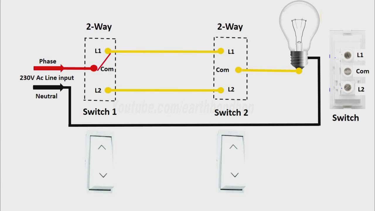
There doesn't seem to be enough wires at the various points to be 'standard' 2 way switch wiring, which would have a 3 core and earth cable between each light switch...

so I'm guessing it may be the alternative method, similar to this (ignore the colours)

2-Way-Light-Switch-diagram.jpg


With a permanent live coming in at one of the switches, then 2 wires (the black ones) between each switch, and a switched feed going to the light(s).

From what I can see it doesn't appear that any of the blue wires are neutrals, so they should be marked with brown tape to show they are being used as live conductors. It looks like the smart switches you have don't need a neutral to work, which is handy at least...

It may need further testing and the brief services of an electrician with testing equipment to be sure, but it is possible that the two blues in the middle box are both permanent live in, then the black wires are the two yellow wires in the diagram above between switches - then at the upstairs switch, and downstairs switch there will be a cable, perhaps the brown, which leaves and goes to the lights involved....

The extra blue downstairs may be the feed that then goes on to the porch light switch.

Blue really shouldn't be used to prove permanent live, only switched live, so it may be worth getting an electrician to check the installation out generally if it hasn't been before, in case there are other oddities.

If my suspicion on the wiring is right, then I don't think you can use those switches as you'd like. as when the smart switch is 'off', you would not be getting a live feed to the other switch...

You may need to bypass the switch wiring and look at smart bulbs and remote switches. Or you may be able to use one 2 gang switch in the middle box, and then remote switches at the other points. I think I can see a way of connecting the wires to do that, but need enough time to get my head around it fully before committing to any suggestion.
Thanks for the reply I'll be sure to check it out in the morning. I am out of daylight for today so do not feel comfortable even testing this evening.

I am fine with virtual switches. But the ideal for me would be to have all three floors work separately on single gang switches. Or even just the third floor separate from the bottom two.

I am planning on making the top floor a smart switch anyway, so it would be possible to not connect button two on the middle floor and have it trigger the switch on the top floor. My smart home is all local, so the delay will be fine.

I'll update in the morning, thanks for the really comprehensive reply!
 
Thanks for the pictures, that does help somewhat, though still a little confusing and really needs some more testing to narrow things down.

Firstly, if you don't have every circuit off, assume every cable is live until you can prove otherwise (with a method other than touching them!)

Wagos are just better versions of the little push fit connectors you have - they will do fine instead.

If you set the multimeter to a range that covers 230 volts, and have one probe on one of the connected earths (not the one that is cut off), then the other probe touched to the opposite port of each cable should tell you which are permanent live.

You really should work out which circuits each is on, particularly the blue wire - there may well be a lighting circuit per floor, or an up and down, or split in some other way.

Can you see if the black wires are individually fed into the back box, or are part of a cable, like the brown/blue are?

I suspect they are the 'travellers' between the various 2 way switches, to allow switching from two floors.

The problem will be that the smart switches you have are not set up for 2 way wiring, which requires 3 terminals for 3 wires between each switch.

If so you may have to decide which switches you want to retain, and use virtual switches to control smart lightbulbs. However, that will also cause issues, since if the power to the bulb is switched off, it can't respond to the virtual switch, so you'd likely need to replace all switches with 'virtual' ones, even if they happen to be on the back boxes.

Can you carefully remove the top light switch and see what wires you have in there? I suspect you will have two black ones, and possibly another blue or brown leaving, with maybe another core cut off in the box.

If so, those stray blacks will become live when the switch is in one position, so need to have connectors on them before the circuit is made live again.

There doesn't seem to be enough wires at the various points to be 'standard' 2 way switch wiring, which would have a 3 core and earth cable between each light switch...

so I'm guessing it may be the alternative method, similar to this (ignore the colours)

2-Way-Light-Switch-diagram.jpg


With a permanent live coming in at one of the switches, then 2 wires (the black ones) between each switch, and a switched feed going to the light(s).

From what I can see it doesn't appear that any of the blue wires are neutrals, so they should be marked with brown tape to show they are being used as live conductors. It looks like the smart switches you have don't need a neutral to work, which is handy at least...

It may need further testing and the brief services of an electrician with testing equipment to be sure, but it is possible that the two blues in the middle box are both permanent live in, then the black wires are the two yellow wires in the diagram above between switches - then at the upstairs switch, and downstairs switch there will be a cable, perhaps the brown, which leaves and goes to the lights involved....

The extra blue downstairs may be the feed that then goes on to the porch light switch.

Blue really shouldn't be used to prove permanent live, only switched live, so it may be worth getting an electrician to check the installation out generally if it hasn't been before, in case there are other oddities.

If my suspicion on the wiring is right, then I don't think you can use those switches as you'd like. as when the smart switch is 'off', you would not be getting a live feed to the other switch...

You may need to bypass the switch wiring and look at smart bulbs and remote switches. Or you may be able to use one 2 gang switch in the middle box, and then remote switches at the other points. I think I can see a way of connecting the wires to do that, but need enough time to get my head around it fully before committing to any suggestion.
Hi, so to give you an update, I went through the steps you outline below but it didn't get me any further. I looked in the upstairs light switch and found that it did only have two wires and an earth. There was no third wire for switching or anything.

So I had a play around with downstairs and discovered a way that I could power the porch and give switching control to the downstairs light. You may recall that the top floor light was always working when I connected the two white wrapped wires on the middle floor. I had a further play with this to see if I could give independent control to both the middle and the top floor with no luck.

So I decided to take one of your suggestions and I've made the middle floor completely virtual connecting, with wagos, the two white wraped wires and the two yellow wrapped wires. I then used wagos to cap off the brown wire on the ground floor, the spare black wire on the middle floor and the earth wire on the middle floor. I then put a virtual zigbee switch on the middle floor that controls the light switch on the ground and on the top there is a slight delay of maybe half a second, but I'm happy with the outcome. I've also ordered cheaply for AliExpress the same style from the same manufacturer of virtual switch so that they will match with all the others.

Genuinely appreciate all your help, thank you.
Not what I was expecting on the top switch, so definitely sounds like there's some unusual wiring going on there, but glad you've found a way to get it to work.

Sounds like all the spare wires are capped off now, so everything is safe. If you ever have an electrician in doing other work, then might well be worth getting him to run some tests and work out which wire goes where, purely for future use.

Glad I could help in some way.
 

Reply to Landing Light Switch gone wrong in the DIY Electrical Advice area at ElectriciansForums.net

Similar Threads

I hope someone can help with this as I'm stumped. My landing hallway ceiling (2016-build house) has two rose pendants which I've attempted to...
Replies
7
Views
429
Hi I want to add a light to my attic. There is a single switch on the landing that I want to change to a double switch and then use it to still...
Replies
24
Views
1K
Hi, I’m looking to install 3 meross smart switches for 3 lights: entrance switch: only 1 gang but 3 way switch bedroom switch: 2 gang (1 is 1...
Replies
9
Views
325
Suggestions / solutions please anyone? I have a 2 way switch, Hall and Landing, power being fed on Landing. When the switch is turned on, the...
Replies
2
Views
505
L
WIRING FOR WALL SMART SWITCH FOR CEILING FAN/LIGHT Just bought a smart wall switch for a ceiling fan/light currently connected to a single switch...
Replies
0
Views
702
littletwinn
L

OFFICIAL SPONSORS

Electrical Goods - Electrical Tools - Brand Names Electrician Courses Green Electrical Goods PCB Way Electrical Goods - Electrical Tools - Brand Names Pushfit Wire Connectors Electric Underfloor Heating Electrician Courses
These Official Forum Sponsors May Provide Discounts to Regular Forum Members - If you would like to sponsor us then CLICK HERE and post a thread with who you are, and we'll send you some stats etc
This website was designed, optimised and is hosted by Untold Media. Operating under the name Untold Media since 2001.
Back
Top
AdBlock Detected

We get it, advertisements are annoying!

Sure, ad-blocking software does a great job at blocking ads, but it also blocks useful features of our website. For the best site experience please disable your AdBlocker.

I've Disabled AdBlock