Discuss Wiring a relay?................... in the UK Electrical Forum area at ElectriciansForums.net

HappyHippyDad

-
Esteemed
Arms
Reaction score
5,600
Hello all..

I have been asked to wire a relay into a FCU for a 3kW immersion.

The plan is for the customer to be able to access the immersion over WIFI.

The relay is a Shelly 1pm WIFI relay, 16A 110V - 240V.

I have not wired a relay before, hence asking on here.

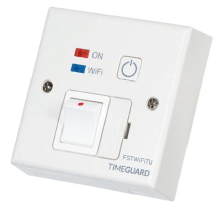
The wiring diagrams on the MI (see pic) show it being used for a light, which will include a light switch. Therefore do I just make a link between the L and SW as seen in my written diagram? Do I need the link, or are these terminals purely so the light could still be used from the switch?

I don't see how I can wire this directly into the FCU for the immersion as the relay has a common neutral, I would therefore loose the double pole function of the FCU. So, I'm assuming the relay would get wired into the load cable coming from the FCU going to the immersion?

Thanks in advance.

Shelly.MI.jpg Shelly.My wiring2.jpg
 
What you suggest looks fine to me.

I would put it on the load side of the FCU as you propose as handier for anyone to isolate later, also just to flick off/on if it needs a hardware reset to get connection going again.
 
What you suggest looks fine to me.

I would put it on the load side of the FCU as you propose as handier for anyone to isolate later, also just to flick off/on if it needs a hardware reset to get connection going again.

If you fit the relay on the load side of the FCU as per your sketchy sketch, then you still have D.P isolation by the FCU.

Do the Shelly relays come with a box, the website appears to show them being hidden inside a continental socket?
Thankyou both :)

What do you think about the link between L and SW? Does this look like it is needed? I'm a little worried that this just means the immersion is 'on' all the time?

@snowhead The customer seemed to think they are designed to go into the back box of the switch/socket. This is corroborated by some internet sites. I would rather have it in a separate box as it'll be a bit of a squeeze in the FCU.
 
I don't think you should link L and SL - I think that is to allow an external switch input to control the output.

And I think I'd definitely be putting it in a separate box.
 
I don't think you should link L and SL - I think that is to allow an external switch input to control the output.
Looking at the instructions here:
It seems the L1 to L internal path is for power measurement, and then the L to SW link is for the relay that comes out on the 'O' pin (i.e. SW-O is the relay contacts and L1-L the measurement CT or similar). So it is linked up as it should be.

And I think I'd definitely be putting it in a separate box.
Yes, definitely!

The dimensions of 41 x 36 x 17 mm suggest it could go in a 25mm deep back-box with a blanking plate as a cover, maybe even a 1+1 back-box so FCU through the the relay unit all in the one area?
 
I don't think you should link L and SL - I think that is to allow an external switch input to control the output.

And I think I'd definitely be putting it in a separate box.
That's also my take on it - it's basically a manual override so needs to be kept unconnected (or connected to any old normal switch for use as a manual override, of course.). It's not the clearest of instructions! L1 may need linking to L, too, as I suspect that may be the internal power??

LEGEND:
N - Neutral input (Zero)/( + )
L - Line input (110-240V)/( - )
L1 - Line input for relay power
SW - Switch (input) controlling O
O - Output
I think you may be right.

Other diagrams on the net showed a link between L and L1, this was when it was used to supply a socket.
 
Yes, looking at it again maybe that link is not needed. Probably best to play with it before you try to install at a customers site!

I do wonder what will happen when the related 'cloud' service is eventually discontinued?
 
Thanks all for the posts.

I did feel a little silly posting as I assumed this was just really obvious. It proves not to be quite so straight forward which I feel a tad pleased about :)

I shall endeavour to update, although it's not exactly the most exciting of threads.
 
I think I'd have talked her into a simple 24 hour timer, instant wifi access to something that needs a good hour to warm up seems a bit ott. :)
I agree, Shelly plus relay plus all your time is a hard way to do this.
Buy one of these. Job done
0_252F2_252F4_252F3_252F0243505bc49b985c5a8f2d37bab9148f5d9f2c34_FSTWIFITU_800x.png

Timeguard Wi-Fi Controlled Fused Spur (Tuya Edition) - FSTWIFITU​


(other similar products are available)
 
Related to this thread, I looked at there other products and this looks jolly useful:

I think it can be used with wired networking and no need for "the cloud" so might be handy for small projects needing a degree of automation or power reporting. At £100 or so it is almost worth getting on just to play with!
 
The WiFi relay is rated at 16A, but it will be designed for compactness and a 16A load would probably be pushing the actual relay within towards its limit. I would be interested to know how well they last when operating a 3kW immersion. Might be 100% fine and the electronics might be life expired long before the relay itself. But things burn out with immersion loads that in theory ought to survive, and many peoples' experience of this product will be switching trivial lighting loads etc. In a critical application I would probably go for belt and braces and use it to control a contactor or power relay.
 
I've had the Timeguard wifi switch operating the main (3kW) immersion in a holiday cottage for about 3 years now, and all good. The app is a bit clunky, but has a log of the past 24hrs showing when the load is active (not just the time it's set for - it indicates when current is being drawn), thus showing when the water has reached set temp, so can be reassuring!
 
The relay worked as expected. A link was needed between L and L1.
Only problem was the neutral terminal screw didn't tighten up, so he is returning it. Still, glad I know how to do it now.
Thanks again for all the help.
 

Reply to Wiring a relay?................... in the UK Electrical Forum area at ElectriciansForums.net

Similar Threads

First, sorry if I'm not in the correxct thread. I'm trying to replace an old switch with a WIFI switch and cannot seem to do it right. There are...
Replies
1
Views
274
super new to these things. i made a drawing to see if this will work. if so which ice cube relay should i use. the picture shown is a hoa switch...
Replies
1
Views
955
Hi Total novi e but have wired multiple light switches previously and survived :) I've bought a nice WiFi enabled dinner switch for a new LED...
Replies
11
Views
939
Hi folks, I’m new to the forum and it’s this issue that lead me here. So first things first. I was looking to wire in a Smart Relay at the rose...
Replies
2
Views
920
Hi all, I need help/feedback. I am modifying a machine. I have added an aluminium profile frame (enclosure ) to a machine (the machine will be...
Replies
2
Views
781

OFFICIAL SPONSORS

Electrical Goods - Electrical Tools - Brand Names Electrician Courses Green Electrical Goods PCB Way Electrical Goods - Electrical Tools - Brand Names Pushfit Wire Connectors Electric Underfloor Heating Electrician Courses
These Official Forum Sponsors May Provide Discounts to Regular Forum Members - If you would like to sponsor us then CLICK HERE and post a thread with who you are, and we'll send you some stats etc

Electrical Forum

Welcome to the Electrical Forum at ElectriciansForums.net. The friendliest electrical forum online. General electrical questions and answers can be found in the electrical forum.
This website was designed, optimised and is hosted by Untold Media. Operating under the name Untold Media since 2001.
Back
Top
AdBlock Detected

We get it, advertisements are annoying!

Sure, ad-blocking software does a great job at blocking ads, but it also blocks useful features of our website. For the best site experience please disable your AdBlocker.

I've Disabled AdBlock