I have a project that uses a stepper motor (200 steps/rev, bipolar, 2A/phase). Right now I am using a chopper driver (that uses PWM as I understand it) to limit the current to 2A using 12VDC as the supply. However the motor is being controlled by the pi, with a python script sequencing the steps. This is very loud, and clunky as the pi stutters occasionally and can only drive the motor so fast.
My goal for the project is to design a custom PCB that will incorporate all the components for the project into one board that plugs into a raspberry pi with a ribbon cable. That'll involve a few resistors, capacitors, the components for a Real Time Clock, and the motor drivers.
From what I gathered so far, I want a PWM driver to microstep the motor. There are a few boards available, but I'd like to understand the process a bit better, especially since I plan on designing my own board.
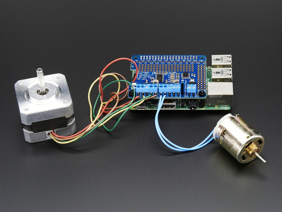
Adafruit sells a board that uses an LED PWM, PCA9685, which then drives a motor driver IC (BH6578FVM-TR). The BH6578FVM-TR is limited to 1.2A.
I want a limit of 1.5-1.8A, which is another reason I'll need to design the board myself.
So with all that (much too long) background info, here are my questions:
1.Is there a better choice than the LED PWM? Or are there any downsides to the LED PWM that justify the increased cost of a different part?
2.Can I figure out what resistors, caps, diodes, etc I'll need to incorporate into the board from the product datasheet? I'm a fast learner, but this is a new area for me. I can copy what Adafruit did for their board, but that seems risky when incorporating the higher power driver
3.Is it as easy as finding a motor driver IC that handles more power and putting it where the BH6578FVM-TR is in the Adafruit design?
4.Do I have to program the PWM chip., or does it just accept a set of predetermined commands from the I2C bus and act predictably?
Any and all advice welcome, and if someone has a good guide or tutorial I should read before tackling this, I'm grateful for the direction.
Thanks for your time
My goal for the project is to design a custom PCB that will incorporate all the components for the project into one board that plugs into a raspberry pi with a ribbon cable. That'll involve a few resistors, capacitors, the components for a Real Time Clock, and the motor drivers.
From what I gathered so far, I want a PWM driver to microstep the motor. There are a few boards available, but I'd like to understand the process a bit better, especially since I plan on designing my own board.
Adafruit sells a board that uses an LED PWM, PCA9685, which then drives a motor driver IC (BH6578FVM-TR). The BH6578FVM-TR is limited to 1.2A.
I want a limit of 1.5-1.8A, which is another reason I'll need to design the board myself.
So with all that (much too long) background info, here are my questions:
1.Is there a better choice than the LED PWM? Or are there any downsides to the LED PWM that justify the increased cost of a different part?
2.Can I figure out what resistors, caps, diodes, etc I'll need to incorporate into the board from the product datasheet? I'm a fast learner, but this is a new area for me. I can copy what Adafruit did for their board, but that seems risky when incorporating the higher power driver
3.Is it as easy as finding a motor driver IC that handles more power and putting it where the BH6578FVM-TR is in the Adafruit design?
4.Do I have to program the PWM chip., or does it just accept a set of predetermined commands from the I2C bus and act predictably?
Any and all advice welcome, and if someone has a good guide or tutorial I should read before tackling this, I'm grateful for the direction.
Thanks for your time


