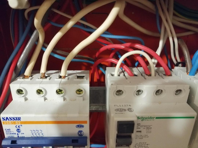
ABB ESB40-40-230AC/DC - https://new.abb.com/products/GHE3491102R0006/esb40-40-230ac-dc-installation-contactor
The ABB contactor is a good make and well suited. It is a silent or hum-free design and the 40A AC1 (resistive and low inductance or PF nearly 1) rating for the contacts is excellent for your application.
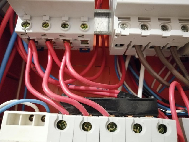
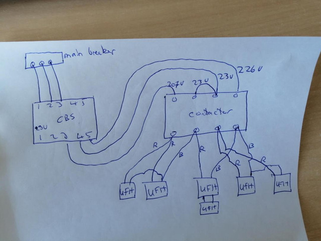
I don't know what the Uruguay electrical regulations stipulate for switching to countenance single pole switching. At the moment all your contactors are used for double pole switching; this is certainly necessary for those UFH elements wired across L1 and L2 but for those across L1-N and L2-N single pole may be allowed - I just don't know. However, double pole is to be preferred because it maintains uniformity of wiring scheme for the UFH system and there is some advantage in splitting the arc across two pairs of contacts when they open to prolong life. I would not opt for single pole switching.
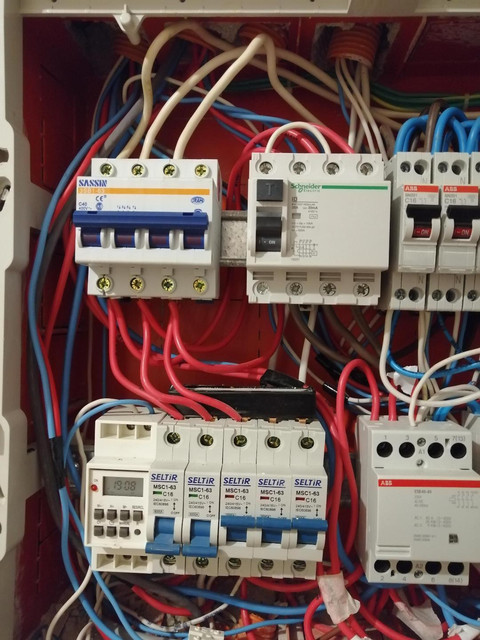
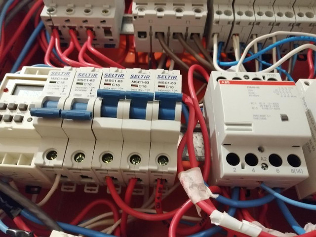
The aforesaid means that to continue with double pole switching you would need to obtain a 6 pole contactor if you wanted one to switch three sets of heating elements in the way a showed in my last diagram. Such a contactor I is rarer than 4 pole and thus I expect pricier. I don't know if you can obtain a silent 6 pole contactor.
Using one contactor to switch 2 or more UFH zones has two drawbacks; if it fails you have lost all heating and when it closes or opens the large current change will cause a noticeable and perhaps troublesome voltage transient in your home and maybe to your neighbours. Far better to sub-divide the load switching over 3 contactors to reduce the magnitude of each transient step. Already I notice that you have quite a variation in supply voltage as loads in your home are powered on and off which indicates a higher supply impedance than is typical in the UK. Switching the UFH zones as one will be noticeable and annoying.
Which leads on to the idea of switching each zone directly using a wifi 'contactor'. In theory this is possible but great care is needed to ensure the power contacts have an adequate AC1 rating and can cope with frequent switching during the day. I'd have to see the specification to comment further. Would it be silent? Would I do it in 'one step'? - no, because I like my functionality appropriately realised in the best possible way. I speak from an industrial background so in the domestic setting one might be more inclined to economy of components.
Sorry about the rather long-winded reply - I have nothing else to do.
")
The ABB contactor is a good make and well suited. It is a silent or hum-free design and the 40A AC1 (resistive and low inductance or PF nearly 1) rating for the contacts is excellent for your application.
I don't know what the Uruguay electrical regulations stipulate for switching to countenance single pole switching. At the moment all your contactors are used for double pole switching; this is certainly necessary for those UFH elements wired across L1 and L2 but for those across L1-N and L2-N single pole may be allowed - I just don't know. However, double pole is to be preferred because it maintains uniformity of wiring scheme for the UFH system and there is some advantage in splitting the arc across two pairs of contacts when they open to prolong life. I would not opt for single pole switching.
The aforesaid means that to continue with double pole switching you would need to obtain a 6 pole contactor if you wanted one to switch three sets of heating elements in the way a showed in my last diagram. Such a contactor I is rarer than 4 pole and thus I expect pricier. I don't know if you can obtain a silent 6 pole contactor.
Using one contactor to switch 2 or more UFH zones has two drawbacks; if it fails you have lost all heating and when it closes or opens the large current change will cause a noticeable and perhaps troublesome voltage transient in your home and maybe to your neighbours. Far better to sub-divide the load switching over 3 contactors to reduce the magnitude of each transient step. Already I notice that you have quite a variation in supply voltage as loads in your home are powered on and off which indicates a higher supply impedance than is typical in the UK. Switching the UFH zones as one will be noticeable and annoying.
Which leads on to the idea of switching each zone directly using a wifi 'contactor'. In theory this is possible but great care is needed to ensure the power contacts have an adequate AC1 rating and can cope with frequent switching during the day. I'd have to see the specification to comment further. Would it be silent? Would I do it in 'one step'? - no, because I like my functionality appropriately realised in the best possible way. I speak from an industrial background so in the domestic setting one might be more inclined to economy of components.
Sorry about the rather long-winded reply - I have nothing else to do.