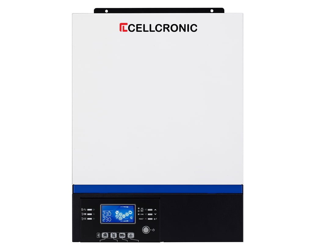
So I have completed a rewire on a house that had stood empty for several years, vandals had stripped the place including pulling all of the cables from the tubes.

So rewire was a case of replacing cables, board, sockets and switches.
However the place is no longer connected to the electricity grid and the new owner had a €20k solar system, inverter and a rack of 9 batteries installed even before we turned up.

My question, the solar guys cabled everything up and as we were starting supplied us a feed from the inverter, we connected into our new board and as circuits were pulled in we connected them, tested and carried on.

Its all up and running now but I cannot for the life of me get my head around why the Neutral in the house seems to be the live phase ( volt stick ) and on a meter get 240v between Neutral and earth nothing between live and earth ( via ground rod )? if I switch the cables around the issue remains ?? the output from the inverter seems to always want the neutral side of our board / cabling to be the live what ever way the output is connected.

It feels very odd and now we have a back up generator to bring on line which will auto start if the inverter sees the solar charge low as well as the batteries, how can I know which way to align the phase output from the generator and the solar?? ...help guys
Please tell me the details of the inverter.
 
Please tell me the details of the inverter.
See attached the inverter details, I realised after writing this the back up generator issue was not a problem as it connected to the input side of the inverter so that parts is up and running so happy with that, the polarity issue remains the same though.
 

Attachments

  • 1.jpg
    1.jpg
    158.8 KB · Views: 67
  • 2.jpg
    2.jpg
    165.6 KB · Views: 59
  • 3.jpg
    3.jpg
    240.6 KB · Views: 63
Are lightning surge protectors connected between array dc cables and earth electrode?

is inverter chassis box connected to earth electrode?

Are frames of solar panels connected to earth electrode?

what type of panels?

what potential differences exist between live ac or dc conductors and earth electrode when you use an approved voltage tester AVT rather than volt stick or multimeter?

This hybrid inverter is a transformerless type which means there is no galvanic isolation between the dc and ac circuitry. There will be inevitable ac and dc leakage currents to earth which will in combination determine the potentials of the dc and ac conductors with respect to earth.

I have found the manual for the inverter to read and will be in touch later or tomorrow. The AVT test results would be helpful if you can do it.
 
A quick look at the manual says this:

11. GROUNDING INSTRUCTIONS -This inverter/charger should be connected to a permanent grounded wiring system. Be sure to comply with local requirements and regulation to install this inverter.

However, it is not clear if they are referring to the chassis (which should obviously be grounded) or the AC neutral line which is (by the definition of "neutral") grounded at some point, with that point being the definition of the TT/TN-S/TN-C-S sort of earthing arrangement.

I don't know the rules in Portugal, but in the UK you are only allowed to have a single connection between neutral and earth, and that is always done by the DNO (power supply company) for any mains power, or if you have a sizeable backup generator then you would do it there but you must have a transfer switch that switches neutral as well as the line conductors so the N-E link is always outside of your installation and at the source of power.

My suspicion then is it relies on the incoming AC supply's neutral as a means of grounding for the resulting AC from the battery/solar source, so in the absence of a grid supply that ought to be grounded via a suitable rod, but I suspect you might have to ask the manufacturer of the inverter.
 
Are lightning surge protectors connected between array dc cables and earth electrode?

is inverter chassis box connected to earth electrode?

Are frames of solar panels connected to earth electrode?

what type of panels?

what potential differences exist between live ac or dc conductors and earth electrode when you use an approved voltage tester AVT rather than volt stick or multimeter?

This hybrid inverter is a transformerless type which means there is no galvanic isolation between the dc and ac circuitry. There will be inevitable ac and dc leakage currents to earth which will in combination determine the potentials of the dc and ac conductors with respect to earth.

I have found the manual for the inverter to read and will be in touch later or tomorrow. The AVT test results would be helpful if you can do it.
 
Further to my last question on type of panels: The manual says this:

WARNING: Because this inverter is non-isolated, only three types of PV modules are acceptable: single crystalline, poly crystalline with class A-rated and CIGS modules. To avoid any malfunction, do not connect any PV modules with possible current leakage to the inverter. For example, grounded PV modules will cause current leakage to the inverter. When using CIGS modules, please be sure NO grounding.
 
With the inverter completely disconnected ( L and N) from the main board, measure the insulation resistance of the house installation L-cpc and then N cpc - all house appliances disconnected/turned off and light switches off/lamps removed - cpc connected to earth electrode for these two tests. if you can remove all lamps do tests with light switches on.

It could be there is low IR L-cpc/earth compared with N-cpc/earth. When connected to Board the floating L and N from the inverter output will assume potentials with respect to earth dependent on the magnitude of the IR to earth - higher IR to earth will have higher potential to earth.* That the higher potential is always on the N side suggests low IR somewhere on the L side of house wiring. Or may be a faulty appliance with low IR in the same way.

* (The two house IRs form a potential divider connected across house wiring L and house wiring N with the midpoint connected to earth). So same result if output of inverter swapped over.
 
Last edited:
Okay so the main grid network is totally absent, vandals took the cables across the field years ago, so there is no power, neutral or earth via the power company.

So the solar panel company basically fitted it all up and cabled to our board ( we connected it ) with a live neutral and earth ( maybe)

The solar company was a contractor from 250 miles away and they fitted it up, got paid and left never to return.
We looked through the system to help the client and determined the solar panel frames are earthed back to the inverter earth point, from this point the battery cases are earthed, from the same point is the cable they left for us to connect into the new board.

So we wired the house, as if it was connected to the mains network but basically the ouput from the solar is wired into the main trip ( single phase )

We ran a 16mm earth cable outside and placed 2 x earth rods set 5 meters apart, this also was connected in at the board.

We wired the back up diesel generator into the 230v input at the inverter and connected the auto start lead between the two.

The system works, came on line just fine, charges the batteries and supplied the whole house, one day whilst working there we let the batteries go low ( covered the solar panels) and late in the day the generator started up and perfect the batteries started to charge and the house was still powered.

So the only fly in the ointment as were is the polarity issue ?

Interestingly when we opened the inverter up the live and neutral outputs were connected the wrong way around, aha I thought, but no it made no difference correcting them, makes me think they were trying to solve the issue too??

Oh and there are no lightning arresters fitted, to be honest the whole solar pv panel thing here is very badly serviced, generally by wannabes who have jumped on to the band wagon as such, I am not wanting to get into it as we have plenty of work anyhow but as a spark I should get a working knowledge of it really.

Thanks in advance for any advise.

Ps will try a volt check between the ac and dc with my Martindale meter
 
Assume IR readings are 1MOhm and 22MOhm as shown in attached diagram then Neutral will always be 220V wrt to earth and Line 10V wrt to earth, even if inverter output swapped over.

You probably see same thing when generator powers home if its output is floating.

Be mindful that many white appliacnes like washing machines have mains electromagnetic interference suppression filters which connect across L, N and E so these need to be unplugged for IR tests. It is not unknown for these to fail but we can consider that later if necessary.
 

Attachments

  • portugalsolar.png
    portugalsolar.png
    39.2 KB · Views: 56
Last edited:
Assume IR readings are 1MOhm and 22MOhm as shown in attached diagram then Neutral will always be 220V wrt to earth and Line 10V wrt to earth, even if inverter output swapped over.

You probably see same thing when generator powers home if its output is floating.

Be mindful that many white appliacnes like washing machines have mains electromagnetic interference suppression filters which connect across L, N and E so these need to be unplugged for IR tests. It is not unknown for these to fail but we can consider that later if necessary.
That is what I wanted to hear, good to get it right in my head, I have spent the last +5 years getting my UK electrical practises converted to Portuguese ways yet still keeping safety and quality in mind, way too many builders here do electrical installs!

On the whole I like it, tubing houses from boards to every socket and switch makes for great / easy rewires.
Most of the commercial work we do is almost the same as UK but Solar, Omg I have seen some terrible work.

Thanks for you input and the sketch, very much appreciated.
 

OFFICIAL SPONSORS

Electrical Goods - Electrical Tools - Brand Names Electrician Courses Green Electrical Goods PCB Way Green 2 Go Pushfit Wire Connectors Electric Underfloor Heating Electrician Courses Heating 2 Go
These Official Forum Sponsors May Provide Discounts to Regular Forum Members - If you would like to sponsor us then CLICK HERE and post a thread with who you are, and we'll send you some stats etc

Advert

Daily, weekly or monthly email

Thread starter

Joined
Location
Portugal
If you're a qualified, trainee, or retired electrician - Which country is it that your work will be / is / was aimed at?
All Other Countries (This Is English Speaking Website Only - WE don't mind Google Translate Users :)
What type of forum member are you?
Practising Electrician (Qualified - Domestic or Commercial etc)

Thread Information

Title
Help with solar pv polarity
Prefix
N/A
Forum
Solar PV Forum | Solar Panels Forum
Start date
Last reply date
Replies
19

Advert

Thread statistics

Created
Algarve Sparky,
Last reply from
Algarve Sparky,
Replies
19
Views
3,985

Advert

Back
Top