P

Paul.M

This is for the people still in or has just left their electrical education or for those of us that need a refresher in domestic earthing arrangements. It's all very well looking at prity diagrams in college and in books but its different when your out in the field for the first time. Hope this thread helps you and I hope that other members will post up their pictures of main incomers/earthing so others can learn and understand this subject better. I wish I could refer to something like this when I was in college.


First of all we have 3 types of earthing arrangements, TN-S, TN-C-S and TT.

TN-C-S
tncs1.jpg


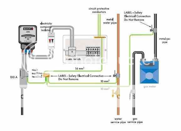
This is where the main earth cable from the main earth terminal (met) is connected to the neutral at the suppliers main fuse. A good way to remember the name of this arrangement is to think of the C meaning COMBINED.


TN-S
image-3.jpg


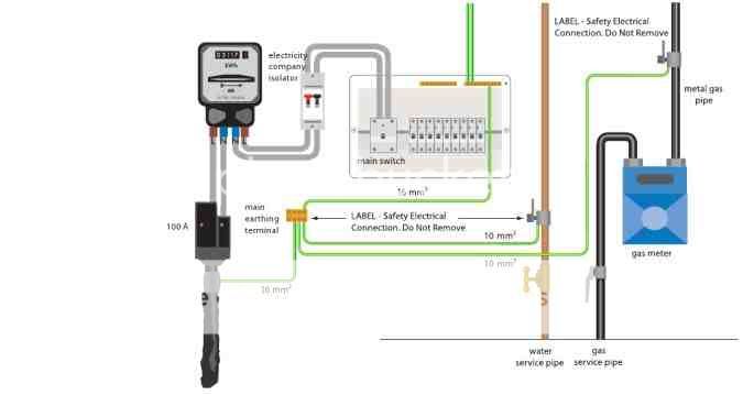
This is where the main earth cable from the met is clamped or solderd to the steel of the SWA or the led outer sheath of the incoming supply cable. Again a good way to remember this is to think that the S stands for SHEATH.

TT
electrics_earthing_supply_types_and_bonding_meter_pos_tt-1.gif


The main earth cable from the met is connect to an earth electrode (aka earth rod). This is because not all properties are supplied with a TN system by the supplier so we have to insert a rod into the ground.


Notice how the earth cable on the TN systems go back to the main incomer, one goes to the main fuse (TN-C-S) and the other goes to the incoming cable (TN-S). If the main earth cable doesn't go back to the fuse or incoming cable it will be a TT. This is the simplest way I can put it without going into extended detail.


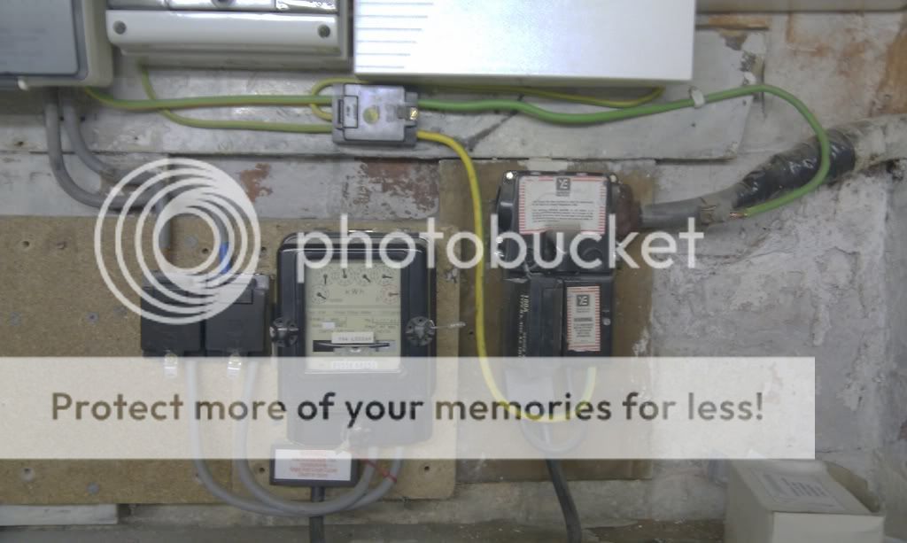
Now that we've seen some prity diagrams (am I starting to sound like a teacher lol) we will now look at real world photos that are not as straight forward as the diagrams.


First example, is it a TN-S or a TN-C-S or both?

IMAG0082-2.jpg
 
Last edited by a moderator:
So what do YOU think about them??

Hi Engineer54. The first few posts were along the lines of a quiz, so I was trying to get people guessing. Perhaps it's so obvious it isn't worth asking, in which case I'll go now! I'm no electrician, but have been told what the system is by the DNO. It's fairly unusual and outdated as far as I know, and I thought people might be interested (as the thread suggested). I have more pics, I was waiting to see if folk needed more. I was ultimately going to ask this question which I don't know the answer to: how safe is it and what can I do to make it safer!
 
Last edited:
Hi folks. yes, intermediate pole with earthing. Didn't mean to mislead anyone. The red tape isn't masking anything, it was covering the exposed copper at the meter tails. I'm guessing that the greenish wire to right of main fuse is the earth. I am trying to post more pics, but have just upgraded machine to Windows 8 and am lost!
 
Hahaha....Well I wouldn't have know what it was if it came up and kicked me in the nuts and told me!
I'm still non the wiser.
I'll keep an eye on the IET forums in case you ask over there.
 
I found this comment on the IET forum (thanks Archy S): "Up in Scotland as one of the DNOs, CEW or (SEN) is a Continuos earth wire earthing system given to consumers who have an earth loop higher than 0.35 ohms. ie 3 wire single phase system consisting of a phase, neutral and a separate earth. If PME they'd just get a phase and a combined earth/neutral."

This doesn't sound as if it's much better than a TT system, does it? Can anyone say whether I ought to be having my sheds TT'd, based on this comment? I am about to have a RCD-protected split CU installed. 30mA RCDs sufficient? Having seen some shoddy workmanship up here, I want to know exactly what an electrician should be suggesting!
 
How's the earth actually made, and where does it join neutral (if at all).

I'm comparing with our supply, which is the same type of pole mounted 11kV transformer but in our case we're connected by underground split concentric to provide TN-S (DNO called this CEW as well). As explained by the DNO our transformer's neutral on the LV side is connected to an earth cable/rod/spike or something at the foot of the pole.

A previous house, served by overhead 240V, only had L and N overhead with a locally provided earth.

In this case, are they really providing Earth on an overhead cable?
 
Last edited:
I found this comment on the IET forum (thanks Archy S): "Up in Scotland as one of the DNOs, CEW or (SEN) is a Continuos earth wire earthing system given to consumers who have an earth loop higher than 0.35 ohms. ie 3 wire single phase system consisting of a phase, neutral and a separate earth. If PME they'd just get a phase and a combined earth/neutral."

That'd be TNS then. (?) :confused:
Further research needed, when I'm totally C[SUB]2[/SUB]H[SUB]5[/SUB]OH free! :-)
 
"Up in Scotland as one of the DNOs, CEW or (SEN) is a Continuos earth wire earthing system given to consumers who have an earth loop higher than 0.35 ohms."

I'm not sure if it's the same thing he was meaning, but SSE publishes a target of max 0.35 ohms for TNCS, but up to 0.80 for TNS. It doesn't necessarily mean that TNS will be over 0.35 though, ours is 0.29.
 
How's the earth actually made, and where does it join neutral (if at all).

I'm comparing with our supply, which is the same type of pole mounted 11kV transformer but in our case we're connected by underground split concentric to provide TN-S (DNO called this CEW as well). As explained by the DNO our transformer's neutral on the LV side is connected to an earth cable/rod/spike or something at the foot of the pole.

A previous house, served by overhead 240V, only had L and N overhead with a locally provided earth.

In this case, are they really providing Earth on an overhead cable?

Hi aesmith, thank you for replies. I am only versed in basic electrics. Can you tell me were I should b looking to answer your question "how's earth made, and whre does it join neutral". I have a basic understanding of the more obvious systems TN-S etc. I could take more pics.

I have been told that this overhead earth is still common up here. I had a response on another forum about split concentric: "It looks like an old TN-S to me. Separate overhead earth (no longer done). You could report lack of earthing and see if they will replace your aged supply with a SPLIT concentric drop (TN-S)". I decided to post on this thread because it was specifically targeting earthing systems. I did try to get the chap from SSE to explain more to me, but he seemed unwilling.
 
"Up in Scotland as one of the DNOs, CEW or (SEN) is a Continuos earth wire earthing system given to consumers who have an earth loop higher than 0.35 ohms."

I'm not sure if it's the same thing he was meaning, but SSE publishes a target of max 0.35 ohms for TNCS, but up to 0.80 for TNS. It doesn't necessarily mean that TNS will be over 0.35 though, ours is 0.29.

This is interesting, thanks. I was hasty in my response about the resistance and the thought of TT, best to be quick whilst kind folk are in the process of helping you out!
 
Hi aesmith, thank you for replies. I am only versed in basic electrics. Can you tell me were I should b looking to answer your question "how's earth made, and whre does it join neutral". I have a basic understanding of the more obvious systems TN-S etc. I could take more pics.
You may be misunderstanding me, I'm not an electrician but I have taken a keen interest in our earthing arrangements because of the need to take supplies out to some outbuildings with a lot of extraneous metalwork so I made it my business to get a definitive answer.

I see you're supplied by SSE as well, but I guess there are regional differences. I contacted them ([email protected]) to ask what sort of earth they provided. Their first response was that I should get it checked by an electrician, but they also said they were installing PME and could check whether we could be "upgraded". When I asked to follow that up they arranged for their guy to come to site, who clarified the system and also took the Ze reading. I think you have to be a bit persistent, you're probably dealing with someone non technical in the first instance, so you need to give them a reason to pass your question onto the technical team. Are you concerned about the safety of your supply from an earthing point of view?
 
Hi aesmith, yes, my main concern is with the safety of the earthing. I was originally concerned that the system was TT or similar, and so the CU required a 100mA RCD. At present it has no RCDs at all. As someone else said, the earthing arrangement that I do have here could deteriorate underground. Similarly with the outbuildings, I wondered if earthing rods were required and am still unclear on that one, because some folk say you can never have too much earthing. If he system here is TN-S, then I should worry less. SSE is installing a new substation couple of miles away from here right now, so I will ask again for someone more technical to visit. Thank you for your help.
 
The three wire is an old way of N→E connection. It moves the LV earth rod away from the MV earth rod.

Hi Tony, thank you for this. However, being a layman (but really wanting to know more about the subject) I don't understand where the HV would be at the house, let alone the earths. Could you point me in the right direction of a simple explanation please? Many thanks.
 
The three wire is an old way of N→E connection. It moves the LV earth rod away from the MV earth rod.

Come on Tony, please explain what CEW is in simple terms, maybe with one of your infamous drawings! (If you're feeling in a generous mood! :-) )
I just can't visualise it.
 
Just because you asked Archy

How it was explained to me at the EMEB collage.

Around each of the earth rods there will under earth fault conditions be a voltage gradient in the ground. In order for the MV and LV to be interconnected the LV earth electrode must be <2Ώ. Higher and the site is referred to by the DNO as hot and no direct MV→LV earth connection is allowed.
Therefore the LV earth has to be moved away from the MV equipment earth. This is to prevent a MV earth fault migrating to the LV system.

My drawing for OH supply
OHearthingzones_zps22959b1b.jpg


DNO drawing for ground mounted
Substation_zpscacb0f7a.jpg
and when you think about it Tony...its just common sense isn`t it...

differing potentials n all that lot...
 
and i`ll say this as well Tony..

one of the neighbours up until recently had issues with extranious in his house with voltage sitting on it..

then he said one day the DNO came out and were doing something...
ever since then the extranious in his house has been clear....

hmm.....
 
The DNO’s also have another crafty trick with MV OH earthing. You may have seen section switches on OH lines. If you look there will be an earth running from the switch metalwork to the ground. It isn’t a rod, there will be a mat.
The idea is that the ground the operator is standing on is at the same potential as the switch metalwork. Where it gets tricky is approaching the switch, I was taught “the shuffle”. You don’t go striding up to the switch as there could be a ground voltage gradient, you shuffle towards it not putting one foot fully in front of the other.

PS I don’t like MV OH lines.
 
Cows are more sensitive to the gradient effect because of the distance between their legs (this applies to some TV 'celebrities' as well). Luckily most cows don't need to operate MV switchgear - they normally stick the the LV stuff. Daz
 
PS I don’t like MV OH lines.[/QUOTE]

Oh boy, this is all filling me with confidence, not! So, as a poor soul who has to live with an overhead supply, is there anything I can do/have done to make it safer? Apart from avoid crawling about on all fours! The DNO is clearly not concerned until some poor sod discovers a fault!
 
The advantage of having sheep and cattle in the field is you know there’s a ground voltage gradient around the switch. Dead sheep and cows tend to give it away.
 
Oh boy, this is all filling me with confidence, not! So, as a poor soul who has to live with an overhead supply, is there anything I can do/have done to make it safer? Apart from avoid crawling about on all fours! The DNO is clearly not concerned until some poor sod discovers a fault!

If you know there's a fault, supplies gone off etc. Don't go nosing around the MV gear, simple as. If you're that woried, talk to the DNO. If you're on a farm then it's worth a phone call.

Remember I’m talking of fault conditions, not the everyday life of country folk.
 

OFFICIAL SPONSORS

Electrical Goods - Electrical Tools - Brand Names Electrician Courses Green Electrical Goods PCB Way Green 2 Go Pushfit Wire Connectors Electric Underfloor Heating Electrician Courses Heating 2 Go
These Official Forum Sponsors May Provide Discounts to Regular Forum Members - If you would like to sponsor us then CLICK HERE and post a thread with who you are, and we'll send you some stats etc

Advert

Daily, weekly or monthly email

Thread Information

Title
Earthing Arrangements Explained + Photo's
Prefix
Forum
UK Electrical Forum
Start date
Last reply date
Replies
177
Unsolved
--

Advert

Thread statistics

Created
Paul.M,
Last reply from
LastManOnline,
Replies
177
Views
151,898

Advert

Back
Top