-
Pro's OnlyElectricians Arms Electrician Talk How to Access The Arms Domestic Electrician Industrial Electricians Wiring, Theories, Regulations Engineering Chat Periodic Testing Problems Electricians Downloads Commercial Electricians Security (Access-Only) Access Private Area Business Related Advice Certification Schemes Electrical & PAT Testing
You are using an out of date browser. It may not display this or other websites correctly.
You should upgrade or use an alternative browser.
You should upgrade or use an alternative browser.
- Thread starter KAZ786
- Start date
-
- Tags
- alternative driver led led driver

Welcome to the forum.
I haven't done a detailed search for equivalents but there seem to be some similar products coming up by googling the part number. Not all have the same current and voltage range so to confirm suitability, we need to discover what current has been set on that driver and what the forward voltage of the panel is.
The current is being programmed with a local resistor, and AFAIK the resistor values are the same across all LEDset products, so any model of LEDset driver that includes the set output current and LED forward voltage in its working range will suit, once that resistor is put into the new driver. Do you have any specs on the panel? And what is the resistor value - we can probably decode that to a current setting.
Alternatively, Osram technical might be able to confirm the part number of a drop-in replacement. They would probably be my next call.
Resistor value 16k to gnd. in photo? Is that a blue band?And what is the resistor value - we can probably decode that to a current setting.
or is it a gold band to start and 6k?
I've almost certainly not read it correctly !
Brown, green, black, red, gold. 15k @ 5%
This driver was around 10 years ago, and seems to have been superseded by Dali compatible versions, but these still appear to incorporate the LED set feature, so maybe the current model with Dali could be used? With the same value resistor? Any thoughts anyone?
To find the original data sheet, Google search: "product-datasheet-ot-150220-240700-lt-e.pdf"
The LEDset interface is described in this application note:
I was hoping to find a way of divining the output current set by that 15k resistor, but I'm not sure that's possible from the info here!
KAZ786 - Do you have any technical info on the LED load you want to drive from the replacement driver?
Last edited:
Thanks, you all, I initially thought it would be easy as a new driver replacement, but when I couldn't find the exact part knew I would need some tech knowledge to figure suitable alternative.
Since the first driver packed in a few months, another 3 lights have started starting to flicker, hence relooking at options to sort this out.
For the LED panel load, I will have to double-check, I did have pictures but can't seem to find them. I will need to reopen the lamps
So, am I understanding this right, that I will need a LEDset driver matching the set output current and voltage and use the current resistor, will I need anything extra for the Dali drivers?
Just on a side thought, the lights are currently being used through the breaker rather than the override switch or BMS system, could this be causing the drivers to go faulty prematurely?

Thats useful. So the lamp needs 605mA and will have about 115V across it.Here we go, had on my old phone.
The Osram driver seems to be spec'd to provide this, but I don't know if the 15K resistor is the correct value for 600mA
The fact you are seeing a failure and flickering, maybe the set is getting towards end of life (thinking about the driver possibly being 10 years old), or maybe the driver is not suited to the lamps (or the other way round). I don't see why the source of power (eg direct from breaker or through BMS) should have any effect on the reliability of the lamps, other than them being left on when they needn't be!
It might be worth trying to find a constant current driver capable of being set to 600mA (or built for 600mA), and with the output voltage going up to at least 120V, and rated say 75W. It seems extravagant to buy Osram Dali enabled versions if you don't need that.
The 500mA version of this range is the nearest i can see for a fixed output, assuming they dont want dimming.
They are cheap enough to give it a try
Thank you all again for your time on this matter.
what do you recon on the following;
These are coming up in the £50.00 range, is this cheap, and why the 500ma over 700ma?
The 500mA version of this range is the nearest i can see for a fixed output, assuming they dont want dimming.
They are cheap enough to give it a try
what do you recon on the following;
Just to say that the first Meanwell one has a 700mA fixed current output, which is too much for your 600mA rated LED panel.
The original black Osram driver module has galvanic isolation (reinforced) between mains input and the output. As far as I can see all the long thin Osram ones you list say they have no galvanic isolation between mains in and the output. I'm concerned that would be a safety issue.
So I'm afraid I wouldn't leap at any of them yet!
Yes I think it would. Also it's likely that the programming resistor from the old one could be transferred to this. But I don't know if any of the other control terminals, Dali etc. need to be left disconnected (or not) once the o/p current is set.
But it's not in stock!
500mA is less than 600mA so not going to stress the LEDS,Thank you all again for your time on this matter.
These are coming up in the £50.00 range, is this cheap, and why the 500ma over 700ma?
what do you recon on the following;
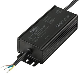
Tridonic Linear Outdoor LCO 75W LED Driver fixC L SNC2 (500mA)
A fixed output built-in LED driver providing a 500mA output current at a 92% efficiency. This driver was designed for luminaires of protection class I.
This one might just do:
 www.bltdirect.com
And there is a beefier version at a bit more money.
www.bltdirect.com
And there is a beefier version at a bit more money.
I'm not sure if it will work out of the box without being (NFC) programmed first! The current is set with a resistor as per the original one. There's loads of technical info on the above website but I haven't looked through it all.
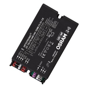
75W Osram Optotronic Programmable LED Driver 35-115V
Optotronic 1DIM NFC outdoor driver by Osram can be used to produce a 35-115V and run to a power of 75 watts maximum. Ideal for industrial application.
I'm not sure if it will work out of the box without being (NFC) programmed first! The current is set with a resistor as per the original one. There's loads of technical info on the above website but I haven't looked through it all.

Tridonic Linear LED Driver LC 75W 250-550mA flexC lp EXC Tridonic 28001808
Shop the Tridonic Linear LED Driver LC 75W 250-550mA flexC lp EXC, model number 28001808. Enjoy reliable and efficient performance for your lighting needs.
Any thoughts on above
Looks good to me. Gives 550mA with current selecting resistor of 0 ohms, ie a link, so you don't need to buy a programming resistor! Seems good to go.Tridonic Linear LED Driver LC 75W 250-550mA flexC lp EXC Tridonic 28001808
Shop the Tridonic Linear LED Driver LC 75W 250-550mA flexC lp EXC, model number 28001808. Enjoy reliable and efficient performance for your lighting needs.www.bltdirect.com
Any thoughts on above
Only think I didn't see was anything about isolation of the output from the mains input, but I think it's implied.
Try one!
If you are going for that type of form factor (they would typical be inside a linear light fitting, then why not
 www.bltdirect.com
8.33K resistor gives 600mA same minimum voltage so no downside
www.bltdirect.com
8.33K resistor gives 600mA same minimum voltage so no downside
Tridonic Non-SELV 100W Constant Current LED Driver (250-700mA)
An IP20 rated constant current LED driver from the Tridonic EXCITE Non-SELV series. This driver is IP20 rated and has an adjustable output current between 250 and 700mA.
E2A: see posts below, the following might be incorrect due to the differences between Gen 1 & 2 configuration.
I am not convinced that the LED is presently running at 605mA. The Osram LEDset guide gives the resistor value as:
Rset [Ω] = (5 V/Iout [A]) x 1000
For 605mA that would be 8.3kΩ and although I can't see the colours on that resistor clearly enough to say what the value is, it doesn't look like 8.2 kΩ. The band that Brian sees as green, I see as blue, which would make it 16kΩ leading to a lamp current of 310mA, i.e. it might be significanly underrun (which could be a factor in the LEDs all outlasting the drivers.) I would want to double-check that before choosing an alternative driver.
Last edited:
I see that band as a blueish green or a greenish blue. Could be either TBH, but 15k is the standard value, although 16k is in the E24 series, of course.The band that Brian sees as green, I see as blue, which would make it 16kΩ leading to a lamp current of 310mA,
It's definitely one or the other.
Thank you Lucien for the cautionary words.I am not convinced that the LED is presently running at 605mA. The Osram LEDset guide gives the resistor value as:
Rset [Ω] = (5 V/Iout [A]) x 1000
For 605mA that would be 8.3kΩ and although I can't see the colours on that resistor clearly enough to say what the value is, it doesn't look like 8.2 kΩ. The band that Brian sees as green, I see as blue, which would make it 16kΩ leading to a lamp current of 310mA, i.e. it might be significanly underrun (which could be a factor in the LEDs all outlasting the drivers.) I would want to double-check that before choosing an alternative driver.
The formula you use above is for Osram "Gen 2" devices.
But the OP's part number I think indicates a Gen 1 device according to the Osram bumf?
See below - I'm not clear if this changes anything or not - your thoughts would be appreciated please.

Good spot, I think you're right and I've edited the above post. Can we discover the relationship of resistor to current for Gen. 1 drivers?
I found this (description! of link in my post #7) see below:Good spot, I think you're right and I've edited the above post. Can we discover the relationship of resistor to current for Gen. 1 drivers?
My attempts at unravelling this from the 274uA current, (presumably from 12V) - and I really haven't understood this - suggested someting like 7V across Rset, which would be driving the lamp a bit over 400mA.

Post crossed with yours Lucien!
I thought I had worked out the source impedance of the 274uA and I had a potential divider of that and Rset which led to a voltage across Rset that I mention above.
Clearly something wrong with that!! Yes - it's a constant current source DUH! Prefer your version.
Last edited:
Oops, post crossed with yours.
It seems the Gen1 interface sets the fraction of the rated output current, not the absolute current, in the relationship: Iout = Inom ((Vset-1)/9). Vset can be derived from an active voltage source in a remote control, optionally referenced to the driver's +12V aux supply, or can be created passively by a resistor driven by a constant 274μA bias current that flows out of the control terminal. Thus for a 16kΩ resistor:
Vset = 274μ * 16k = 4.4V
Iout = 700 * ((Vset-1)/9) = 263mA
That's an even lower fraction of the panel's rating and is starting to sound unlikely.
To set a Gen1 driver of 700mA rating to 605mA with a resistor, one would need:
Vset = 605/700 * 9 +1 = 8.8V
Rset = Vset/274μ = 32kΩ or 33kΩ as the nearest preferred value.
Perhaps we are not seeing the colours on the resistor correctly, but I can't resolve them to anything like 33kΩ
Last edited:
hi,
coming back to this after a couple of years;
resistor colors are as follows Orange,blue, black,red, brown
bltdirect.com
Is this still an option
coming back to this after a couple of years;
resistor colors are as follows Orange,blue, black,red, brown
Tridonic Linear Outdoor LCO 75W LED Driver fixC L SNC2 (500mA)
A fixed output built-in LED driver providing a 500mA output current at a 92% efficiency. This driver was designed for luminaires of protection class I.
Attachments


The resistor value appears to be 36K 5%, a little off Lucien's 33K sum above.resistor colors are as follows Orange,blue, black,red, brown
If it is 36K, I calculate it's programming the power supply to produce 684mA, somewhat over the target 605mA.
Maybe that's why lamps were suffering?
Yes I think so.Is this still an option
The Tridonic driver will give 500mA so the lamps will produce a little less light output, but they ought to last longer!
Sadly these drivers are now discontinued, been looking for a couple of 100W versions and had to resort to Ebay.
The replacements are current set by NFC programming which you can get done but there is a charge. No sure of the available steps and you may get closer to 600mA rather than settling for 500mA
If you go to the Tridonic website its straight forward to choose a suitable driver
The replacements are current set by NFC programming which you can get done but there is a charge. No sure of the available steps and you may get closer to 600mA rather than settling for 500mA
If you go to the Tridonic website its straight forward to choose a suitable driver
thank you for your replies.
I opened another lamp and the driver is somewhat different, (in picture) it has no resistor, do i need specific software to program these ones.
This one is working, i wad just testing to see the led's are working fine before ordering the replacement driver, which they are.
I opened another lamp and the driver is somewhat different, (in picture) it has no resistor, do i need specific software to program these ones.
This one is working, i wad just testing to see the led's are working fine before ordering the replacement driver, which they are.
Attachments

Without a resistor it delivers 700mA, which is more than we were assuming the fitting needed.thank you for your replies.
I opened another lamp and the driver is somewhat different, (in picture) it has no resistor, do i need specific software to program these ones.
This one is working, i wad just testing to see the led's are working fine before ordering the replacement driver, which they are.
That might contribute to shortening the life of the fitting?
The tech info is here: https://www.led-bg.com/uploads/docu...tion-guide-4dimlt2-led-drivers_1441816016.pdf
You don't need software to program it, the documentation says it is still settable with a resistor, and to get it to supply 600mA, you would need an 8k2 resistor between the "LEDset" terminal and the "LED-" terminal.
Alternatively if you can find any info that suggests it's OK to drive the LED fittings at 700mA, just continue to use and replace the Optotronic ones without adding any resistor.
Last edited:
How are these lights controlled ?
Do they dim or are they fixed output?
Do you turn them on with a simple switch?
Reason for asking is that they do appear to be using quite complex drivers for simply on/off
Do they dim or are they fixed output?
Do you turn them on with a simple switch?
Reason for asking is that they do appear to be using quite complex drivers for simply on/off
Good question - I thought the difficulty is that the LED fittings require about 115V to give the desired brightness, and budget drivers I've looked at can't provide the necessary voltage to produce the desired current.How are these lights controlled ?
Do they dim or are they fixed output?
Do you turn them on with a simple switch?
Reason for asking is that they do appear to be using quite complex drivers for simply on/off
There may be a simple 600mA 75W (115V) driver out there, but with a quick look I haven't found one that I'd trust! (there are some real cheap bare boards with extravagant claims!)
The Tridonic Outdoor range are brilliant drivers for high voltage. I have used around 100 on a project and they have been bullet proof apart from one which was powering a long row of tree lights that got attacked by lawnmower man.
Tridonic have, unfortunately (and i can understand why) made their fixed output range now multi fixed by NFC programming. They have updated their Dali to Dali2 and made them NFC programmable. The drivers are not expensive.
What i have found is that it is the lamps that used to be always available at 350mA or greater now they go as low as 200mA, so when you are trying to power a number of lights at 200mA this can mean an oversized driver i.e. a 100W driver is only a 100W driver at 500mA becoming a 30W driver at 200mA... lol
You can probably tell i am learning my way through how to replace drivers that have either expired or the lamp types have changed.
Even sadder is the demise of Lucian who tried to help on the first page.Sadly these drivers are now discontinued,
Sorry to here. May he rest in peace.Even sadder is the demise of Lucian who tried to help on the first page.
Timed through MBS, with override switch, which is the main method of operation. I have not seen any dimming controls.How are these lights controlled ?
Do they dim or are they fixed output?
Do you turn them on with a simple switch?
Reason for asking is that they do appear to be using quite complex drivers for simply on/off
The data sheet recommends paring them with Optotronic drivers, Also mentioned was with max current of 1050ma so i guess the 700ma would be fine.
I opened a third lamp out of curiosity, and it has a different led set and is wired direct with 5 cores with no resistor too, any thoughts?
Attachments


Similar threads
- Replies
- 13
- Views
- 430
- Replies
- 5
- Views
- 230
OFFICIAL SPONSORS


These Official Forum Sponsors May Provide Discounts to Regular Forum Members - If you would like to sponsor us then CLICK HERE and post a thread with who you are, and we'll send you some stats etc
Advert
Thread Information
Thread Tags
- Tags
- alternative driver led led driver
Advert
Advert
TrueNAS JBOD Storage Server
-

-
-
 Understanding TrueNAS JBOD Servers: A Comprehensive Guide
- Started by Dan
- Replies: 8