Could you swap over S1 and S2 and tell me if the problem moves position?
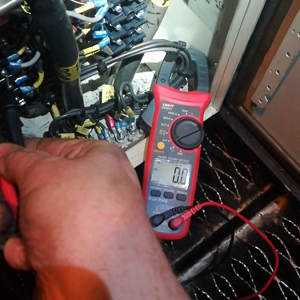
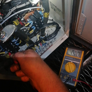
I suspect the hold-on functionality internal to S2 is defective which means only the pull on coil is doing any work to operate S2 - but the pull on coil becomes de-energised when the power contacts S2 close - so to keep the power contacts closed the hold-on coil must be energised. Check the coil resistance of S2's hold on coil. Check it has 110V to energise it - if it does not then trace the control wiring to it backwards to find out where a Normally Open contact is not being closed.
Or something like this - off to watch the apprentice now. Will look again afterwards.
") Having seen the type of contactors,i would have suggested testing both the pulling and holding resistances.
Having seen the type of contactors,i would have suggested testing both the pulling and holding resistances.")