Guest viewing is limited
R

rryles

I'm trying to understand my options when it comes to protecting ELV circuits, in particular control/signalling/communications type.

As I understand it there are three methods: SELV, PELV and FELV. I know that sometimes SELV is required due to the location. PELV seems to be a combination of ADS and ELV, so requires earthed CPCs everywhere. I'm not too sure about the requirements of FELV though.
 
Thanks picollo, but the link refers to the 16th edition and makes no mention of PELV.
 
SELV as you rightly say is used in areas of increased risk for example zone 0 of baths showers and swimming pools, both lives and earth being segregated form all other circuits and fed from a recognised source such as: a safety isolating transformer, battery or other devices that ensure the outgoing supply can not exceed 50Vac or 120V dc

PELV virtually the same but earth not segregated, PELV could be used in zone 1 of bathrooms for example

FELV is used where either SELV or PELV is not required of the circuit can not meet the requirements of SELV or PELV, eg where equipment such as transformers, controls, relay swithces do not meet the criteria for insulation against higher voltages or where the supply does not meet the criteria for PELV or FELV

A FELV insulation test current is 500V dc as against 250V dc for SELV or PELV
 
Selv - Seperated extra low voltage, by far the most common in most transformers etc etc, no potential to earth on the secondary side.

Pelv - Protective extra low voltage, secondary has a Potential to earth, never seen anything employing this, im sure there is just ive never come across it.

Felv- functional extr low voltage, HAs a functional earth, usually carrying leakage current. you wont see these unless you work for BT, the Functional cunductor is normally Cream in colour.
 
...

Pelv - Protective extra low voltage, secondary has a Potential to earth, never seen anything employing this, im sure there is just ive never come across it.

...

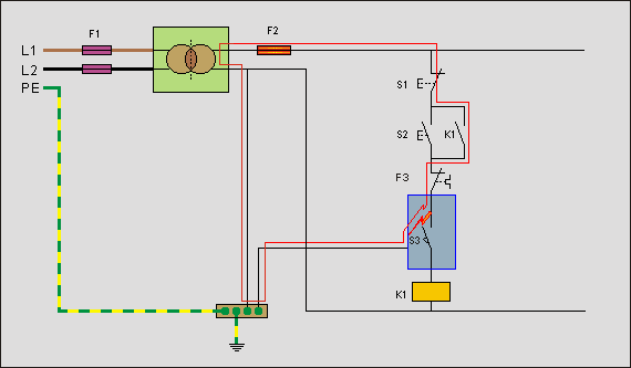
Typically found in automation where 24v ac/dc control circuits are used. Look at the example below of a typical motor starter.

F1 = Primary fuse
F2 = Secondary fuse
F3 = Motor overload
K1 = Motor contactor + aux contact
S1 = Stop pushbutton
S2 = Start pushbutton
S3 = Limit switch in metal body/enclosure + earthed (perhaps a motor guard)

A fault to the earthed enclosure of S3 would provide a fault path to enable the fuse F2 to pop.

pelv_macchine_02.gif


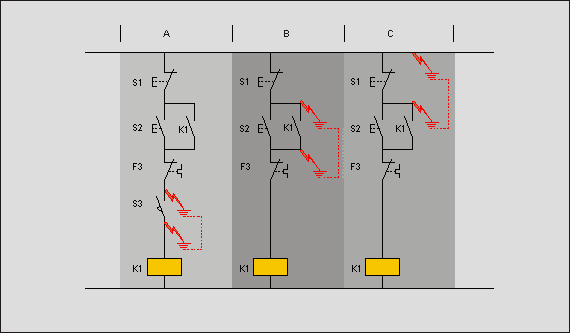
In this next diagram... imagine if the enclosure wasn't earthed;

in sector A, the wires at S3 are trapped in the enclosure or the enclosure is soaking wet after being washed down, a fault would result in the contact S3 being shorted out but being earthed pops the fuse.

in sector B, the contactor aux K1 would be shorted thus self-energising K1... without the start button being pushed. Also on release of a stop push, K1 will re-energise!

in sector C, K1 is allowed to energise in the correct way but a short across S1 will prevent K1 de-energising!

pelv_macchine_01.gif
 

OFFICIAL SPONSORS

Electrical Goods - Electrical Tools - Brand Names Electrician Courses Green Electrical Goods PCB Way Green 2 Go Pushfit Wire Connectors Electric Underfloor Heating Electrician Courses Heating 2 Go
These Official Forum Sponsors May Provide Discounts to Regular Forum Members - If you would like to sponsor us then CLICK HERE and post a thread with who you are, and we'll send you some stats etc

Advert

Daily, weekly or monthly email

Thread Information

Title
SELV, PELV and FELV
Prefix
N/A
Forum
Electrical Wiring, Theories and Regulations
Start date
Last reply date
Replies
7

Advert

Thread statistics

Created
rryles,
Last reply from
Dan,
Replies
7
Views
76,551

Advert

Back
Top