-
Pro's OnlyElectricians Arms Electrician Talk How to Access The Arms Domestic Electrician Industrial Electricians Wiring, Theories, Regulations Engineering Chat Periodic Testing Problems Electricians Downloads Commercial Electricians Security (Access-Only) Access Private Area Business Related Advice Certification Schemes Electrical & PAT Testing
You are using an out of date browser. It may not display this or other websites correctly.
You should upgrade or use an alternative browser.
You should upgrade or use an alternative browser.
")
I plan to buy temperature controlled soldering iron in future, but for now I don't need it, current one is sufficient, it does ok job.
I will buy desoldering wick to see if it's better for smaller joints, I just couldn't desolder them with pump.
Solder wick is very useful. Beginners can sometimes pull PCs tracks off though so be careful.
[automerge]1593359129[/automerge]
Should have said PCBs but too late to edit it.
Last edited:
How to solder to my standards. Another example: 6mm² tap into an unbroken run of 16mm².
The strands of the main run are parted, 3 to one side and 4 to the other, and the tap cable passed through the gap. The gap is then closed up with pliers and the strands wrapped around the main cable, again split into 3 & 4. The wraps are tightened with pliers and soldered. For this demo I have set the tap cable at right-angles for clarity; it can just as easily be soldered in a Y-position.
In this case I used a stick of tinman's solder (40/60) and a touch of Fluxite. My choice of iron here was the trusty 240W Henley; it's a good allrounder and when working on the bench its weight is not much of a hindrance. OTOH the heavy tip stores a lot of heat and can raise a large job to working temperature very quickly, so anything that is too large for this tends to be blowlamp or pot territory.
After soldering, the work was cleaned of flux and residues with a rag and thinners, then the tap cable dressed into the Y position to enable the adhesive-lined heatshrink to be fitted. Note that with just ordinary heatshrink, it is not possible to make the joint watertight, as there will be a void between the two parallel cables. Either a Y-boot or some additional hot-melt is needed to seal it fully. Finally a cable tie holds the tap cable to the run to avoid stretching the heat-shrink while handling.
I'll write about desoldering from a PCB next time.
#
Last edited:
Elecmox
DIY
I think it's too small for PCB.
Elecmox
DIY
I have bought solder wick and I managed to desolder LED diode I previously couldn't with sucker (in red circle).
I have tried to desolder mouse buttons (in green circles) with wick but it just didn't absorb solder. Solder just didn't want to melt, I then added some solder on all joints and then I used pump and I managed to remove solder but I still can't remove buttons, there are some small fragments of solder holding component legs.

I solder two wires onto LED diode to practice, I hope I did it right. I first tinned wires and then I just put soldering iron on diode's legs and joined wires. Is that process ok?

I tested connection, LED diode lights up! Yeah!?

I have tried to desolder mouse buttons (in green circles) with wick but it just didn't absorb solder. Solder just didn't want to melt, I then added some solder on all joints and then I used pump and I managed to remove solder but I still can't remove buttons, there are some small fragments of solder holding component legs.
I solder two wires onto LED diode to practice, I hope I did it right. I first tinned wires and then I just put soldering iron on diode's legs and joined wires. Is that process ok?
I tested connection, LED diode lights up! Yeah!?
This is often needed, I do it all the time.I then added some solder on all joints
Maybe not enough heat, but this is another common problem. Try moving the component slightly as the residual solder cools, so that it makes a weak bond. Sometimes it helps to push the component lead one way or another with the iron, to stop it pressing against one side of the plated-through hole to which it will tend to bond again even with very little solder. If there's just 0.1mm clearance, the solder bond will be much weaker. It's always a compromise between damaging the PCB with too much heat while removing the solder, and damaging it by pulling the tracks and vias off because too much solder is left behind.I still can't remove buttons, there are some small fragments of solder holding component legs.
I first tinned wires and then I just put soldering iron on diode's legs and joined wires. Is that process ok?
Yes, for connections that can be completed quickly. Tinning is really to prepare the surface, ready for fresh solder to be applied to make the joint, and with that fresh solder comes fresh flux. Always tin both parts if possible. In this kind of situation where you are just lap-jointing two wires, you can usually leave enough solder on the wires that no more needs to be added (and therefore do the work with two hands instead of three. But for this to work properly, the flux still needs to be active, not burnt or oxidised, when the parts are brought together and the solder re-flowed. If you can tin the parts in under one second each, the flux should still be OK, otherwise you will want to add a touch more solder or flux to re-flow. Half a second to tin and one second to re-flow is about the maximum.
Elecmox
DIY
I am not sure if my soldering iron has enough heat, since this is my first ever, but I couldn't melt solder of components.
I am not sure if my 30 watts iron really gives 30 watts of power, it's a cheap iron from local DIY store, its Womax LP-30.
When I do tinning, tin melts right away.
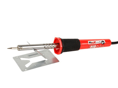
I am not sure if my 30 watts iron really gives 30 watts of power, it's a cheap iron from local DIY store, its Womax LP-30.
When I do tinning, tin melts right away.
If you have a reel of old style 60:40 tin-lead solder then it melts at a lower temperature than the lead-free used on most electronics these days. That might be a reason.When I do tinning, tin melts right away.
Elecmox
DIY
Yes, I have 60/40 1mm tin.If you have a reel of old style 60:40 tin-lead solder then it melts at a lower temperature than the lead-free used on most electronics these days. That might be a reason.
What temperature or soldering iron power is needed for lead-free solder?
[automerge]1593504645[/automerge]
Unfortunately, tip is not replaceable.The iron probably has enough power for the PCB work you are doing, but I would try a bigger tip for the bigger joints. A bigger tip transfers more heat to the joint.
I can, but there aren't different tips in DIY store for this iron.
It would be worth you getting hold if one to save struggling. Can you order from Ebay or Amazon?
Elecmox
DIY
I've never change tips before, do you change just tip or whole pen?It would be worth you getting hold if one to save struggling. Can you order from Ebay or Amazon?
There are tips here in stores, but I don't know if they are suitable.
For example:
Vrhovi za lemilice - InterHIT electronic - http://www.interhit.rs/1461-vrhovi-za-lemilice
I will check that out, I would preffer if I could install more flattened tip, something like this.
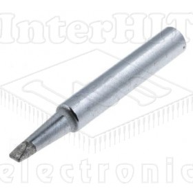
Yes, that would be better than the fine pointed one for larger joints.
I missed out the step ,crafting hole/gap in straight through cable.The strands of the main run are parted, 3 to one side and 4 to the other,
(and damaged conductors attempting to form wanted shape -when cold)
(Also ignore peculiar colour choices -and no sleeving)
--Would this joint ever crystalize grey in time ?--
Point of photo --
practice run - "Have a good laugh"
- heat build-up damaging insulation
- solder wicked along making it hard to shape
( Suspect soldering iron was inadequate - Finished
it off with ....
(More mechanical insulation damage )
Attachments

Elecmox
DIY
Looks like Alien 3.I missed out the step ,crafting hole/gap in straight through cable.
(and damaged conductors attempting to form wanted shape -when cold)
(Also ignore peculiar colour choices -and no sleeving)
--Would this joint ever crystalize grey in time ?--
Point of photo --
practice run - "Have a good laugh"
- heat build-up damaging insulation
- solder wicked along making it hard to shape
( Suspect soldering iron was inadequate - Finished
it off with ....
(More mechanical insulation damage )
bloody hell. that looks like a plumber's disaster.I missed out the step ,crafting hole/gap in straight through cable.
(and damaged conductors attempting to form wanted shape -when cold)
(Also ignore peculiar colour choices -and no sleeving)
--Would this joint ever crystalize grey in time ?--
Point of photo --
practice run - "Have a good laugh"
- heat build-up damaging insulation
- solder wicked along making it hard to shape
( Suspect soldering iron was inadequate - Finished
it off with ....
(More mechanical insulation damage )
Elecmox
DIY
Can I give you my neighbour phone number? He has some problems with wires installations in home.I missed out the step ,crafting hole/gap in straight through cable.
(and damaged conductors attempting to form wanted shape -when cold)
(Also ignore peculiar colour choices -and no sleeving)
--Would this joint ever crystalize grey in time ?--
Point of photo --
practice run - "Have a good laugh"
- heat build-up damaging insulation
- solder wicked along making it hard to shape
( Suspect soldering iron was inadequate - Finished
it off with ....
(More mechanical insulation damage )
bloody hell. that looks like a plumber's disaster.
But at the very least a plumber would use a soldering iron/gun fit for the job and not struggle with an inadequate iron.
 How many times does he have to be told?
But at the very least a plumber would use a soldering iron/gun fit for the job and not struggle with an inadequate iron.
You can lead a horse to water but you can't make it buy a big soldering iron tip.
Will a bigger tip help on a 30W soldering iron? Doubt it.
Yes, it will transfer more of the heat to the joint due to the larger contact area. Admittedly it will still struggle with the bigger things on that PCB.
Elecmox
DIY
The problem (as mentioned in My first soldering! - https://www.electriciansforums.net/threads/my-first-soldering.186729/post-1639486) is I guess lead-free joints that my soldering iron is not capable to melt due to low heating temperature. I have used sides of tip for larger contact area on joint but no success. Only thing that worked was adding 60/40 solder on joint and then melt it and removed with pump.Yes, it will transfer more of the heat to the joint due to the larger contact area. Admittedly it will still struggle with the bigger things on that PCB.
How can you tell is solder lead free or not ?
Visually solder joints on PCB look a bit darker, but maybe it's because of time pass.
I remember melting solder in a candle aged 10 or so.
( I got my father to solder wires to pcbs )
.. Solid wire wrap wire being a pain for losing it's insultion springs to mind .. But shame of end result prevents any memeory !
( I got my father to solder wires to pcbs )
.. Solid wire wrap wire being a pain for losing it's insultion springs to mind .. But shame of end result prevents any memeory !
I remember using fuse wire to wrap cables together before soldering, my mother never did figure out why all the fuse wire out of the broom cupboard was missing, or how the little burn marks got on the eiderdown, or so we thought.
Elecmox
DIY
I bought 60W soldering iron, and now I can easily desolder components from PCB, which I couldn't with 30W iron due to lead-free joints.
I must say that 60W is a bit stronger/hotter then I would like to, I think 50W would be perfect for all. I just need to work a bit faster with 60W.
I must say that 60W is a bit stronger/hotter then I would like to, I think 50W would be perfect for all. I just need to work a bit faster with 60W.
Buying a soldering station as suggested at the beginning of this thread, you can adjust the temperature to that required for the task, it's a false economy to keep buying soldering irons at different wattage's to get over the problems encountered.
Elecmox
DIY
I didn't bought station because I still don't need it, and it's a bit expensive compared to my needs. I could've buy cheaper ZD-99 station for 20 euros, but if I buy station I will buy really quality station, but that's in the future, just not now.Buying a soldering station as suggested at the beginning of this thread, you can adjust the temperature to that required for the task, it's a false economy to keep buying soldering irons at different wattage's to get over the problems encountered.
Add a bit of fan assisted McFrugal fume extraction.I must say that 60W is a bit stronger/hotter then I would like to,
To reduce temperature !
(noticed difference with un-regulated irons working outside in the wind )
For desoldering on PCBs applying some flux from a flux pen to the joints before desoldering will often help a lot. I've been using temperature controlled soldering stations for the last 17 or so years and wouldn't be without now. I do use a standard 80W iron for soldering larger wires such as shown in Luciens example above as they can dump a lot of heat into the joint so it can be soldered fast before all the insulation starts melting. A higher wattage iron is needed for most modern pcbs that have more than one track layer, some multilayer boards can have substantial amounts of copper in the inner layers for power rails that can sink the heat away. If the joint isn't heated up enough the plated through holes can be damaged when the component lead is pulled out.
My current iron for PCB work is a 130W JBC, a fantastic tool, bit rather expensive...
My current iron for PCB work is a 130W JBC, a fantastic tool, bit rather expensive...
As an Amazon Associate we earn from qualifying purchases.
Similar threads
- Replies
- 5
- Views
- 306
- Replies
- 32
- Views
- 1K
OFFICIAL SPONSORS


These Official Forum Sponsors May Provide Discounts to Regular Forum Members - If you would like to sponsor us then CLICK HERE and post a thread with who you are, and we'll send you some stats etc
Advert
Thread starter
- Joined
- Location
- Europe
- If you're a qualified, trainee, or retired electrician - Which country is it that your work will be / is / was aimed at?
- All Other Countries (This Is English Speaking Website Only - WE don't mind Google Translate Users :)
- What type of forum member are you?
- DIY or Homeowner (Perhaps seeking pro advice, or an electrician)
Thread Information
Advert
Advert
TrueNAS JBOD Storage Server
-

-
-
 Understanding TrueNAS JBOD Servers: A Comprehensive Guide
- Started by Dan
- Replies: 8