_q12x_

DIY
I have a electronic board with leds (made by me) that is driving a relay. When that relay is closing it’s contacts, is actually switching the 240V for the light bulb switch in my room. This board is quite long, like 50cm (half a meter). The relay is in the left corner, and the live wires from it goes in behind the board to the hole in the wall for the mains switch. I also have a mild steel sheet behind my board that is grounded. It is shielding the interference of the 50Hz from the live wires from the wall to my sensitive circuit. But even If I have this grounded metal shield behind my board, the live wires from the relay are still affecting my entire circuit board, keeping it ON all the time. If I am disconecting the live wires from the relay, the board is functioning very well. Another IF, is if I disconnect the ground from the metal shield, the circuit board goes nuts. So the shield is doing it's job fine, but only for the live wires inside the wall !!! But not for the wires from the relay to the live switch.
- I want a way to shield these wires !
Thank you !
 
I'm sorry, I kind of understanding what you are saying. But not completely.
I like that the photo is very clear and the movie is ok as well. I really love your osciloscope. Very nice model. I really like it.
So... I understand there is a waveform there, that shape on the osciloscope, and with a spike at the end of it, and that you tell me is some RC waveform. But I dont get the point. I think the point is that rapid fluctuation, will not get interfered by the day light? Or what? I also don't have a propper circuit skematic, so I cant follow what you did there very precisely.
I like that you are trying it but you must be more clear/direct with me. I'm not an electronist, remember? Im an artist and i see things visually and very well pointed. Im Not very abstract thinker.
 
In words and briefly because I ma being pestered by Maud our 9 weeks old puppy - you remember I showed you some near perfect rectangular pulses on my new scope? They were at the output of the 555 clock running at 25kHz. In the latest post, these pulses switch a MOSFET transistor on and off which in turn turns the 4 infra red LED illuminators on my sensor array on and off - equal time on to time off or a 1 to 1 duty cycle/mark-space ratio.

One might expect that the LEDs will produce perfect pulses of ir light - instantaneously on and instantaneously off. Similarly, when these pulses reflect off something in fron tof them back to the photodiodes, the current which flows in these photodiodes instantly starts to flow at a constant value (dependent on the intensity of the received ir light hitting them) and instantly stops when the light turns off.

The little video of the current waveform (actually shows a the voltage this current develops across a resistor) is not instantaneously flowing or stopping. There is a rise time and a decay time. The rise and the decay look the same shape and duration as one would expect from a 1 to 1 duty cycle. What I wanted to show is the benefit of 'seeing' the waveform actually produced by a sensor on the scope. It dispels any notion that it is a rectangular waveform exactly the same as the driving waveform derived from the 555 clock. So this is the signal which the sensor produces and it is a distorted version of the driving waveform. Why is it distorted? Because in electronics (as in many physical systems) there are lags and delays between stimulus (the driving waveform) and current response by the photodiode. No device can actually respond instantaneously - they can respond very quickly indeed but there is always some time required to respond.

The longer it takes something to respond the slower it clearly responds to changes. The predominant reason why the waveform becomes distorted is the photodiode ( and also the transistors and LEDs) have small amounts of capacitance which I hope you know by now tends to slow down a change in voltage to a change in current. Thus we speak of a CR circuit have a time constant which is related to its frequency response and so-called impulse response. For more look at:

https://www.electronics-tutorials.ws/rc/rc_1.html

https://www.electronics-tutorials.ws/rc/rc_3.html

I have not yet begun to tackle the background light problem. If I have time I will make a video of the sensor voltage waveform changing in amplitude as objects move closer or further away from the sensor.

PS: To understand electronics and thus be able to design circuits one must learn some theory. I hope you find this interesting and gives you some insight as to what is happening.

PS2: Something similar was happening with your radio frequency wireless remote.

PS3: When I was a youngster knowing little I would write down all the technical terms I did not know or understand and then look them up in books or ask my uncle to explain them. All you have to do now is google them so it is hardly any effort to find out and learn. Please look up 'impulse response' and explain it to me :)
 
Last edited:
The predominant reason why the waveform becomes distorted is the photodiode ( and also the transistors and LEDs) have small amounts of capacitance which I hope you know by now tends to slow down a change in voltage to a change in current.
THis part is educative indeed. I didnt make the link in my mind exactly as you explain it here, i tell you sincerely. Though I am aware of the fact that EVERY component has it's own capacitance and resistance in a certain procentage, but usually is very-very low. For example, a capacitor has an internal resistance, and a resistor has an internal capacitance, and the other components for example a diode has a bit of both, a bit of resistance and a bit of capacitance when is working. Basically, nothing is perfect flowing the current through them. THat part I knew it already. But the way you put it is good for me to know "small amounts of capacitance tends to slow down a change in voltage" for each component. The thing is, I am a bit overlooking this little detail because the impact or effect is so small, it is insignificative in the big circuit.
For example, if I was stumble over each of these details in my big wings circuit, I would never had make it, or at least push it until this stage is right now.
I respect the fact that you want to teach me something new ! All the help I want from you is to assist me, as well as you can, and if you can, along the road I am already with this projekt.
When I was a youngster knowing little I would write down all the technical terms I did not know or understand and then look them up in books or ask my uncle to explain them.
That is a very smart thing to do. I do it very rarely, "write down the problem". THough as you mentioned, if I have a problem, with today internet I kind of understanding everything i put my mind to. If not 100% then it will be in a big percentage. It will be better than I knew nothing anyway. Haha.
To respond to your question, which is a bit intriguing but is a part of a bigger problem, from what I can see between the lines: about "impulse response". I just read about it. It is very new concept to me. It refers to frequncies, or oscilations. It is basically a shock or a bang. It is containing all the frequencies at once in the impulse part. Then the response part, from what I understand, is based on the component structure to reflect back. It is like a light red filter for example, when you shine white light over it, but under it, you obtain only the red light. THat is because it absorbs the other frequncies of the light but let pass only the red through it. THat is the response part. But it is applied not for a piece of glass like in my example, but to active components like diodes, or your experimental photodiodes that you measured with that fancy osciloscope which I like very much. Haha
 
Im Not very abstract thinker. Really? You are an artist - second nature I'd have thought. Anyway, have you begun to think about what would be required of a device which followed you around your room: not the technology of its implementation but what would it have to do? How do animals look and see? For a start one might consider the question of 'which part of you'? How would this part be recognised by a device? How would it be followed?

I hope you enjoy the mental stimulation of thinking about it. :cool:
 
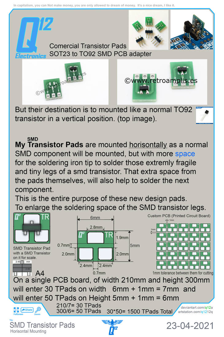
In your mind, why do you think I am writing the top text on EACH of my artpages? Really, why do you think? Or any of you. See? And Im doing it like this for 8 years and people like you are saying, aah, pfff that is nothing, that is not true, that is bullsh*t. And I keep continuing writing my warning there, on the next, and the next, and the next. That's how the real world works. With nothings like me. :) haha.
Screenshot_3.jpg


Screenshot_4.jpg

Screenshot_5.jpg

Screenshot_6.jpg
 
In your mind, why do you think I am writing the top text on EACH of my artpages? Really, why do you think? Or any of you. See? And Im doing it like this for 8 years and people like you are saying, aah, pfff that is nothing, that is not true, that is bullsh*t. And I keep continuing writing my warning there, on the next, and the next, and the next. That's how the real world works. With nothings like me. :) haha.
View attachment 85253

View attachment 85255
View attachment 85256
View attachment 85257

The reason is not capitalism, but your negative attitude in my opinion.
 
I am not getting embroiled in this latest line of discussion. When I have made some more progress on my Version 3 I will post but as I said earlier I am distracted and slowed down by other things at the moment.

Best wishes

Marconi
 
q12x Good afternoon. I spent a couple of hours on my version 3, the one which uses pulsed ir light rather than continuous illumination in versions 1 and 2. The pulsing is about 100kHz. The received waveform produced by the ir sensor array is displayed in yellow in the video clip below. The amplitude of the received waveform, which is the combined output of the four photodiodes, varies with the proximity of the hand. I cannot remember if I showed you this variation before. What I did this afternoon is construct a peak detection circuit the output of which is displayed as the blue horizontal line on my scope sitting on top of the peak amplitude of the yellow waveform. Unless my finders are in front of the array it is detecting the side of my scope. You can see the voltage output by the peak detector in Blue following the amplitude of the received Yellow waveform. It is this Blue signal which I will input to my 8 comparators. I will look at the output of the comparators only when the ir illuminators send a pulse of light in order to distinguish between this illumination and background illumination.

How are you getting on? Regards

marconi
 

Attachments

  • FullSizeRender 9.mp4
    29.8 MB
q12x. Good afternoon Sir.

I thought you might like to see a little more progress albeit at a snail’s pace. You know in Version 3 I pulse the ir illuminators on and off and its is this reflected flashing light which the photodiodes receive as well as any background ir light. The photo current of these photodiodes is converted to a voltage which is passed to a peak voltage detector. I thought I would plot the peak voltage at the output of the detector against distance for ir illuminations on and off. The simple test rig is in the first image and the plot in the second. The white piece of paper in the blue clamp is my test ‘hand’ moved along the 15 inch rule towards the sensor array. The steady voltage in red for ir illuminators off is about 60mV and shows the background ir is making no difference to the peak voltage detector output as the hand is moved. You can see the On peak voltage signal is clearly separated from the ambient only off signal. With further signal processing l hope to make Version 3 tolerant to background ir illumination.
 

Attachments

  • 67A58736-5005-4B55-A701-847E2AE3AAC9.jpeg
    67A58736-5005-4B55-A701-847E2AE3AAC9.jpeg
    496.5 KB · Views: 50
  • version3 peak voltage plt.mp4
    580 KB
Last edited:
q12 A little more progress. The second attachment is a view of the breadboard for Version 3 with circuitry to produced pulsed ir illumination, reception of ir pulsed reflections, peak reflected signal detection and a to d conversion to drive the rule of 8 LEDs. You can see in the first attachment the rule of 8 LEDs lighting up as the hand is moved closer and further away from the sensor. This set up is showing permanent pulsation of the ir illumination. The next step is to have repeated bursts of ir pulsed light so that in between bursts one can detect just the ambient background ir received by sensor.
 

Attachments

  • FullSizeRender 12.mp4
    46.5 MB
  • FullSizeRender 10.mp4
    35.2 MB
q12x. Good morning from rainy London.

A little more explanation. Version 3 uses pulsed ir illumination. But of course as well as the pulsed ir being reflected off anything in front of the sensor array producing a received signal component Rp there will also be received a component of reflected ambient ir Ra and direct ambient ir light Da. The total received signal is therefore Tb = Rp + Ra + Da. This is what is detected during the bursts of ir illumination.

Between bursts the illumination is off so what is received is only Ra + Da = T

If then one detects, measures and stores Tb and T, then the difference can be produced Tb - T which is the signal Rp just due to ir illumination reflected off the hand.

The next step then is to measure T.
 
Last edited:

OFFICIAL SPONSORS

Electrical Goods - Electrical Tools - Brand Names Electrician Courses Green Electrical Goods PCB Way Green 2 Go Pushfit Wire Connectors Electric Underfloor Heating Electrician Courses Heating 2 Go
These Official Forum Sponsors May Provide Discounts to Regular Forum Members - If you would like to sponsor us then CLICK HERE and post a thread with who you are, and we'll send you some stats etc

Advert

Daily, weekly or monthly email

Thread starter

_q12x_

DIY
Joined
Location
New York
If you're a qualified, trainee, or retired electrician - Which country is it that your work will be / is / was aimed at?
United States of America
What type of forum member are you?
DIY or Homeowner (Perhaps seeking pro advice, or an electrician)

Thread Information

Title
How to shield a live wire at 240V ?
Prefix
N/A
Forum
UK Electrical Forum
Start date
Last reply date
Replies
384
Unsolved
--

Advert

Thread statistics

Created
_q12x_,
Last reply from
marconi,
Replies
384
Views
37,007

Advert

Back
Top