Search the forum,

Discuss Non-Harmonized cable in Enclosure in the UK Electrical Forum area at ElectriciansForums.net

D

dellboy13

Hi All

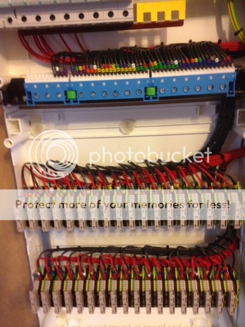
I am currently designing a complete home automation system based around CBUS dimmers and relays. I have now built the enclosures with the dimmers and relays in so I can start programming / testing them. I have going to get a full spark to install the actual cables and connect the lights.
All the CBUS units need breakers feeding them and fuses on their outputs, which I have wired using red and black 1.5mm cables to DIN rail terminators & MCB in the cabinet which are obviously not Harmonized. Is this OK, the spark (when I find one) will do everything external with Harmonized cable!
 
Thanks Charlie, I spoke to the NICEIC this morning and their technical adviser said that it was OK but I have to sleeve each of the cable with Blue or Brown sleeve to indicate use, if I had to do that I might as well rebuild the setup, it would only by 4 or 5 hours work but a pain in the arse to do.
All cables have been individually numbered, what do you think of the install below, should I re-do it or not bother. Fancy a trip down to North Essex to commission it?

IMG_0983.jpg
IMG_0984.jpg
 
If you asked me to do it i would have no problems at all, just an appropriate label on front of the panel, job done


i would not bother sleeving all those cables whats the point, i doubt anyone who lacks the appropriate knowledge would be messing around inside those panels

very neat work by the way!
 
Hi Welchyboy1
The house is just getting out of the ground now, so I will being pinging you a PM in about 5 or 6 months time for a bit of install and commissioning work :smile5:

I had BBC training when I was a junior engineer, so a bit anally retentive on neatness and paperwork :dizzy2:
 
I would be less concerned with the colour of the cables than I would the din rail fuseholder a being exposed when the lid is on. I can't see enough detail in the pic but they don't normally afford the right protection against direct contact. Also what type of fuses are they and what are they there to protect?
What type of cable have you used for building this?

It could have been a lot neater with a bit of panel trunking in there!

Be careful about your choice of electrician, many won't have a clue how to safely test or get meaningful test results on the outgoing cables from such a dimming unit!

Those fuse carriers look like Wiedmuller terminal fuses, they take standard 20mm fuses, they are normally enclosed inside of the panels, I don't think they are certified for external use.

Agree about the (lack of) trunking. :)
 
They look like a standard pull-out fuse carrier, which exposes live parts when withdrawn, which is easily done without the use of a key or tool.
But what are those fuses there for? Will they discriminate with the incoming MCBs? Will they safely handle the fault current? It doesn't take much fault current to make some 20mm fuses literally explode.

There are many questions I would be asking before doing anything with it if I was asked to install it.
Ventilation, IP rating, type testing?
 
No cables have been run in the building yet as it is approximately 225mm high so far (just out of the ground). I was intending to run 1.5mm Twin and Earth for all the home automation circuits (all limited to 1A).
Basically the Dimmers & Relay need to be feed by a 10A MCB and each output needs to be protected by either a 1A Type C MCB or 1A glass fuse (8 dimmer channels per dimmer unit and 12 relay channels per Relay unit). There is a total of 7 dimmer/relay units with 64 outputs to protect, so I was a cheap skate and went for the cheaper fuse option.

The other reason that I went for the din rail fuse option is that I wanted to keep it really neat, so the idea was to run 4" square trunking down the left hand side, then along the bottom, then the cables from the house for the home automation side enter the cabinet from the bottom and feed straight up to the Din rail termination units and fuses, ie each T&E would go straight up to the termination point set, not having to split and go to 3 different locations in the cabinet. - Bad idea or am I on the right track?

Regarding the fuses raised out of the enclosure, I was going to get the lock kit for that cabinet, so I could easily change a fuse if needed but would be locked from general access. I had to raise the din rail to achieve this, if it is not acceptable I can drop it back down and cover the fuses.

I was going to use slotted trunking in the cabinet but there are 4 cabinet in total, so going through from one to another was going to be a little messy, so I thought I would lace them in neatly instead, again is this a bad idea, should I re-do with trunking?

The reason that I am doing this is to configure the system before hand & test and then allow the entire lot to be moved in to the new build (once up) on the large board and speed up the second fix process.
There is also 2 other smaller boards to make up!
 
They look like a standard pull-out fuse carrier, which exposes live parts when withdrawn, which is easily done without the use of a key or tool.
But what are those fuses there for? Will they discriminate with the incoming MCBs? Will they safely handle the fault current? It doesn't take much fault current to make some 20mm fuses literally explode.

They are a flip out type, but they can detach quite easily the (carrier part), here is a pic, we used loads of these for feeding digi multifunction meters and the like when building panels, they are secondary fuses.
 

Attachments

  • 2101884-40.jpg
    7.2 KB · Views: 157
New posts

Reply to Non-Harmonized cable in Enclosure in the UK Electrical Forum area at ElectriciansForums.net

OFFICIAL SPONSORS

Electrical Goods - Electrical Tools - Brand Names Electrician Courses Green Electrical Goods PCB Way Electrical Goods - Electrical Tools - Brand Names Pushfit Wire Connectors Electric Underfloor Heating Electrician Courses
These Official Forum Sponsors May Provide Discounts to Regular Forum Members - If you would like to sponsor us then CLICK HERE and post a thread with who you are, and we'll send you some stats etc
This website was designed, optimised and is hosted by untold.media Operating under the name Untold Media since 2001.
Back
Top
AdBlock Detected

We get it, advertisements are annoying!

Sure, ad-blocking software does a great job at blocking ads, but it also blocks useful features of our website. For the best site experience please disable your AdBlocker.

I've Disabled AdBlock