P

PaulDay

I'm adding a Air Horn setup to my car. I want to keep the OEM Horns operational, which the car uses for the alarm and such, while operating either horn using the steering wheel horn button.

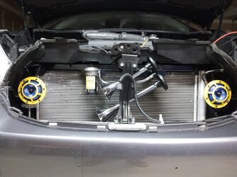
Here's a pic of the Air Horn and compressor mounted before replacing the grill:
IMG_20210103_223106.jpg

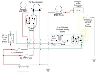
The main reason I'm posting is so that someone with more auto electrical knowledge can verify the circuit design that I've come up with so that the horns work the way I want them to.
AirHornWiring1.jpg

Several things to note:

The Yellow wire coming from the Steering Wheel Horn Button is diverted to the Low Voltage Powered Relay Board as it comes down the steering column, before it goes to the CPU.

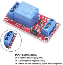
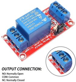
The Low Voltage Powered Relay Board, which I created, is simplified for the sake of the drawing. Here's a link to the LVPRB with more info:

Youngneer 12v Relay Board Relay Module 1 Channel Opto-Isolated High or Low Level Trigger: Amazon.com: Electronics
1609796913901.png1609797098188.png


Thanks for looking. Comments appreciated.

Have a good day.
 
As an Amazon Associate we earn from qualifying purchases.
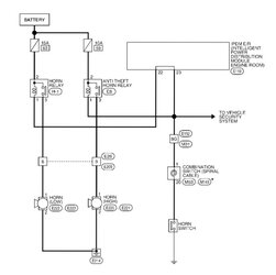
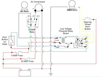
After reviewing the Service Manual wiring diagram dealing with the horn, I realized that the above schematic was wrong and will not work.

Here's a corrected schematic that should would work as desired.

AirHornWiring2.jpg

If anyone sees something wrong, please let me know. Thanks.

Have a good day.
 
i would keep the air horns separate to the OEM wiring.
 
i would keep the air horns separate to the OEM wiring.

Thanks for the fedback.

Basically they are two separate wiring systems. The grounds are tied together in the drawing for simplicity's sake. The only place that they actually interact is where the path to the steering wheel horn button from the IPDM is diverted while going thru the LVPRB.

The only issue that I'm encountering is determining the voltage going from the IPDM to the steering wheel horn button. Usually the CAN system is 5 Volts. If that's the case, then I'll need a slight revision to the circuit to accommodate the lower voltage.

I'm worried about pushing 12 Volts thru the steering wheel horn button. Usually in the new cars, one of the several CAN systems monitors ground connections and then acts accordingly when a button is pressed shorting to ground. It's usually a negative 5 Volts flowing thru these type of CAN wires.

Trying to figure out a way to check before cutting the wire.

Have a good day.
 
Why not use the 12v going to the oem horn? Save messing about with all the other carp.
 
Why not use the 12v going to the oem horn? Save messing about with all the other carp.

Thanks for the feedback.

Unfortunately, it would be wiring mess, having to use two 30 AMP relays and a button that would have to be held down to sound the air horn. My auto electrical installs need to appear as though they are part of the car, not an after thought. All wiring is properly routed and dressed to match the OEM look of the car, along with OEM control buttons.

Here's the OEM horn wiring. Really no easy way because the system uses the two horns for different purposes, only the steering wheel horn button engaging both horns thru the IPDM.

OEM Horn Wiring.jpg

Really the only place is right after the steering wheel button.

Have a good day.
 

OFFICIAL SPONSORS

Electrical Goods - Electrical Tools - Brand Names Electrician Courses Green Electrical Goods PCB Way Electric Underfloor Heating Electrician Courses Heating 2 Go Electrician Workwear Supplier
These Official Forum Sponsors May Provide Discounts to Regular Forum Members - If you would like to sponsor us then CLICK HERE and post a thread with who you are, and we'll send you some stats etc

Advert

Daily, weekly or monthly email

Thread Information

Title
Adding a Air Horn while keeping the OEM Horn.
Prefix
N/A
Forum
Auto Electrician Forum
Start date
Last reply date
Replies
5

Thread Tags

Advert

Thread statistics

Created
PaulDay,
Last reply from
PaulDay,
Replies
5
Views
7,346

Advert