Discuss How to wire these mini speakers? in the DIY Electrical Advice area at ElectriciansForums.net

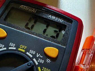
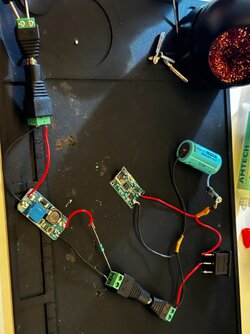
So I’m trying to set the step up converter to 5v and for some reason it only lets me go down to 6v, Is my voltmeter a cheap one and just not reading right or maybe I’m doing something wrong? I tried turning it both ways.
I think it very unlikely to be a problem with the multimeter, and I don't see you are doing anything wrong.
You seem to be using AA cells rather than the lithium battery I thought you were going to use, but I don't think that should be a reason for the higher minimum output voltage,
I'd be more inclined to blame the converter as being the problem (eg component outside tolerance or faulty?)
It might be worth putting a small load across the converter when setting it, to see if that changes its behaviour. Have you got say a 100 ohm resistor, or failing that maybe a small filament bulb of 6V or above, eg Christmas tree light! Put that across the output and see if it stays at 6V, or now will go down to the specified 5V.
I can't see anything in the spec for the amp suggesting it would be OK to run it from 6V unfortunately.
Failing that you could try asking the supplier why it only goes down to 6V ! I wondered if it was something basic such as the adjustment potentiometer slider not going to the end of its track correctly!
I’m using those batteries just to adjust the step up converter, I will be using the lithium battery once it’s to 5v.
I have 5 step up converters(all the same) so I’ll try another one to see if that’s the problem ✌️

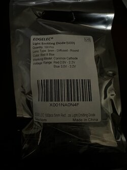
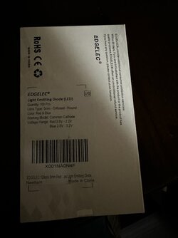
Btw I do have those 3 pin leds, I think it’s a cathode? But idk where I’d have to wire that

Edit: I tried the lithium battery to set the voltage on the step up converter and it’s even worst only goes down to 7.4v :s
 
Last edited:
  • Like
Reactions: DPG
Yes try others! It's a bit concerning that the output voltage is not very stable with changing input voltage. I would have expected better, but I've no knowledge of this part other than reading the ads on the net!
I would encourage you to try a load on the converter, but preferably not by using the amplifier yet!
Good luck with the experiments.
 
Last edited:
I tried another step up converter, and it’s the same thing, and even added 100 ohm resistor made no difference, then I tried a 400 ohm resistor and nothing is making a difference for the output, lowest keeps at 7.3 with the lithium battery, can’t believe how complicated this is 😬
 

Attachments

  • F5060A06-F5FE-4CD2-8479-806252484D69.jpeg
    363.2 KB · Views: 9
  • A684DE08-7D29-45B0-92D1-38D61ACBB636.jpeg
    255 KB · Views: 7
I tried another step up converter, and it’s the same thing, and even added 100 ohm resistor made no difference, then I tried a 400 ohm resistor and nothing is making a difference for the output, lowest keeps at 7.3 with the lithium battery, can’t believe how complicated this is 😬
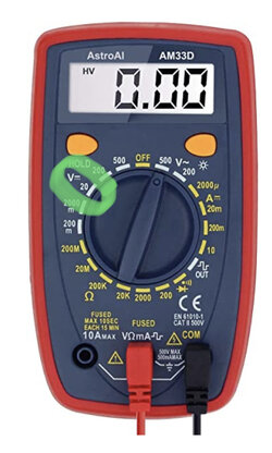
I've just noticed you have the multimeter set on the a.c. voltage (wavy line symbol) setting. There is a d.c. voltage range (straight line symbol) selectable round anticlockwise from your present setting, and you want it set on the 20V range for these measurements.
323CE798-6BB5-4FEB-B5A2-DE0839B4E640.jpeg
You might be getting misleading readings measuring dc on an a.c. range, especially if something is oscillating here. I'm not sure this is the only problem though.
 
Last edited:
I've just noticed you have the multimeter set on the a.c. voltage (wavy line symbol) setting. There is a d.c. voltage range (straight line symbol) selectable round anticlockwise from your present setting, and you want it set on the 20V setting for these measurements.
You might be getting misleading readings measuring dc on an a.c. range, especially if something is oscillating here. I'm not sure this is the only problem though.
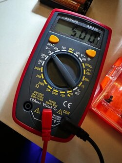
I just noticed the same! I mean I didn’t know I had it wrong until a few mins ago I watched a video and saw someone has the voltmeter setting on the straight line, being a noob sucks lol, it’s reading 5v on the straight line from what I see? So I guess that was the problem?
 

Attachments

  • DF50418B-BA9B-4E6D-AF1A-C920F206D761.jpeg
    288.7 KB · Views: 6
I just noticed the same! I mean I didn’t know I had it wrong until a few mins ago I watched a video and saw someone has the voltmeter setting on the straight line, being a noob sucks lol, it’s reading 5v on the straight line from what I see? So I guess that was the problem?

That sounds better!

I'm surprised at the reading you got on the AC range though. I'm guessing the output of the voltage converter is probably not particularly smooth.
 
See, it's not complicated really 🤪
Off you go!

Have you any info/ part no. on the dual colour led you wanted to connect. I seem to remember from the video it replaced two led's on one of the boards, but I may be misremembering.
 
See, it's not complicated really 🤪
Off you go!

Have you any info/ part no. on the dual colour led you wanted to connect. I seem to remember from the video it replaced two led's on one of the boards, but I may be misremembering.
It’s not, but not knowing this stuff can make it confusing lol.
This is the info for the leds
 

Attachments

  • 5EF527F8-5819-403B-8D8A-83D0C562B0A1.jpeg
    56.7 KB · Views: 4
  • 42CFEFAA-0C03-4400-9BD9-5E7D1E39BDA7.jpeg
    49.9 KB · Views: 4
So I was able to make the speakers work yesterday, everything seems to be working good, the battery didn’t get hot at all or anything 😁 thanks for all the help for real, now I’m just not sure if that 3 pin(once wired) led will tell me when the lithium battery is charged or not 🥴
 
Glad to hear it's working! Well done!

On the matter of knowing whether the battery is charged or not from the dual led, I'm sure you know the dual LED's you've got can't do anything like that on their own.
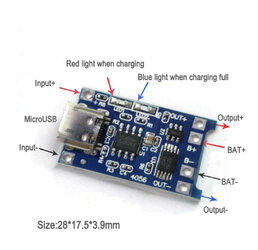
The 4056 charging board has the necessary circuitry and two LED's on it that do this.
What the constructor in the video did for his build was to remove the surface mount LED's from the board, and then wire the pads to the dual LED that he then mounted on the side of his speaker cabinet.

To use your dual LED, you will need to unsolder the surface mount LED's from the board and attach, either directly or via flying leads, the 3-wire diode. I'm thinking the two middle pads may be connected together, and that may then be suitable for the centre wire of your LED, and then connect the other red and blue leads (the right way round!). I think you'll have to prod around with your meter on the ohms range to establish which way round the surface mount LED's are currently on the board (ie which is anode and which is cathode), and if my guess above is correct!.

I haven't found enough info to be able to sketch it for you with any certainty!. I'm afraid I'll leave it with you, and using what you see and can measure about diode polarity's on your 4056 board, hopefully you can get your red/blue diode connected up! Best of luck.
030B5091-BF1D-480D-B9A3-13537157FAE8.jpeg
 
  • Like
Reactions: DPG
Glad to hear it's working! Well done!

On the matter of knowing whether the battery is charged or not from the dual led, I'm sure you know the dual LED's you've got can't do anything like that on their own.
The 4056 charging board has the necessary circuitry and two LED's on it that do this.
What the constructor in the video did for his build was to remove the surface mount LED's from the board, and then wire the pads to the dual LED that he then mounted on the side of his speaker cabinet.

To use your dual LED, you will need to unsolder the surface mount LED's from the board and attach, either directly or via flying leads, the 3-wire diode. I'm thinking the two middle pads may be connected together, and that may then be suitable for the centre wire of your LED, and then connect the other red and blue leads (the right way round!). I think you'll have to prod around with your meter on the ohms range to establish which way round the surface mount LED's are currently on the board (ie which is anode and which is cathode), and if my guess above is correct!.

I haven't found enough info to be able to sketch it for you with any certainty!. I'm afraid I'll leave it with you, and using what you see and can measure about diode polarity's on your 4056 board, hopefully you can get your red/blue diode connected up! Best of luck.
View attachment 106597
I don’t really understand rn, maybe if I keep reading your message lol 🤔 but I didn’t know the board has its own leds I’ll try using those for now, gotta start working on the enclosure anyway
 
I'll leave you to consider wot I rote.
To use your 3-pin led, you will have to remove the two on the board, labelled 'red light' and 'blue light' in the pic above.
But don't take them off the board before finding out which way round they are connected.
So learn how to check diodes with a multimeter!
I know, I know, you just want to get on and make things, but you will need to get your head round stuff on the way too!
 
  • Like
Reactions: DPG
I'll leave you to consider wot I rote.
To use your 3-pin led, you will have to remove the two on the board, labelled 'red light' and 'blue light' in the pic above.
But don't take them off the board before finding out which way round they are connected.
So learn how to check diodes with a multimeter!
I know, I know, you just want to get on and make things, but you will need to get your head round stuff on the way too!
Ok I think I understand now, I’ll try to find out how to check them, thanks 😁
 
  • Like
Reactions: DPG

Reply to How to wire these mini speakers? in the DIY Electrical Advice area at ElectriciansForums.net

Similar Threads

M
It's not car related but is a 12vdc porject, so hope someone can be of help to me on this project I’m a bit of an amateur photographer when it...
Replies
2
Views
2K
mollydog
M

OFFICIAL SPONSORS

Electrical Goods - Electrical Tools - Brand Names Electrician Courses Green Electrical Goods PCB Way Electrical Goods - Electrical Tools - Brand Names Pushfit Wire Connectors Electric Underfloor Heating Electrician Courses
These Official Forum Sponsors May Provide Discounts to Regular Forum Members - If you would like to sponsor us then CLICK HERE and post a thread with who you are, and we'll send you some stats etc
This website was designed, optimised and is hosted by Untold Media. Operating under the name Untold Media since 2001.
Back
Top
AdBlock Detected

We get it, advertisements are annoying!

Sure, ad-blocking software does a great job at blocking ads, but it also blocks useful features of our website. For the best site experience please disable your AdBlocker.

I've Disabled AdBlock