- Jun 29, 2019
- 2,281
- 2,223
- 391,788
- If you're a qualified, trainee, or retired electrician - Which country is it that your work will be / is / was aimed at?
- United Kingdom
- What type of forum member are you?
- Other
- If other, please explain
- Retired Electrical / Electronics Engineer, latterly Quality & Regulatory.
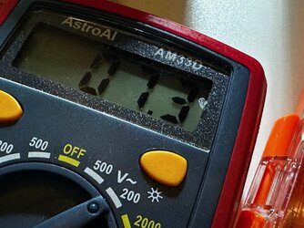
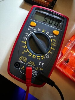
I think it very unlikely to be a problem with the multimeter, and I don't see you are doing anything wrong.So I’m trying to set the step up converter to 5v and for some reason it only lets me go down to 6v, Is my voltmeter a cheap one and just not reading right or maybe I’m doing something wrong? I tried turning it both ways.
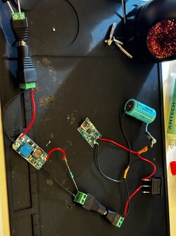
You seem to be using AA cells rather than the lithium battery I thought you were going to use, but I don't think that should be a reason for the higher minimum output voltage,
I'd be more inclined to blame the converter as being the problem (eg component outside tolerance or faulty?)
It might be worth putting a small load across the converter when setting it, to see if that changes its behaviour. Have you got say a 100 ohm resistor, or failing that maybe a small filament bulb of 6V or above, eg Christmas tree light! Put that across the output and see if it stays at 6V, or now will go down to the specified 5V.
I can't see anything in the spec for the amp suggesting it would be OK to run it from 6V unfortunately.
Failing that you could try asking the supplier why it only goes down to 6V ! I wondered if it was something basic such as the adjustment potentiometer slider not going to the end of its track correctly!


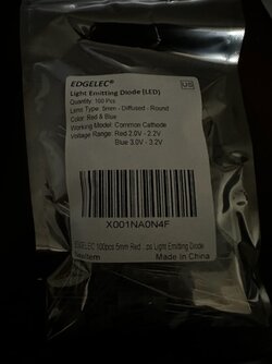


 but I didn’t know the board has its own leds I’ll try using those for now, gotta start working on the enclosure anyway


