Currently reading:
What is the best signal interface for PC ?

Discuss What is the best signal interface for PC ? in the UK Electrical Forum area at ElectriciansForums.net

_q12x_

DIY
Reaction score
212
I mean.... the best and the easiest to use.
I remember back in the 2000's I used a serial interface, I think it was the printer serial port, 25 pins or similar. I believe I even used a mouse port as well, that versatile those systems were back then.
What I could do with it was ... program in C++ and pascal back then, using some imported dll's specific for communication with this serial port, I think it was port 40 or 25? It had a number is all I remember. And I could link to it any transistor base, back then I was working exclusively with BJT's, to light LED's, drive motors, beep some 8ohm I think they were speakers, drive a VU-meter LED bar I think directly from the port pins, without transistors, and also drive IC's , that was the time I learned about multiplexers and expanding the number of output pins. Also input sensors like LDR and buttons. I Loved that kind of easy and straight forward communication.
Today I dont know c++ or pascal anymore, but I am very good in c# and still use VS2010 because its very cool interface and very user friendly overall.
So I want you, to help me first of all, to find the hardware, the port I suppose or something more than a printer port, something more advanced and having more in/out's. The more the better. I want the best you can find for the moment. Best ideas or best adaptations, why not. As long as it's easy and stable to install and use.
And then, the software drivers and possible problems will appear along the way. I can debug a large majority of problems, I grow up debugging computer problems, so I have a 5'th sense for them. Im more concerned about the hardware part and the integration with my win7 that I still run today and my VisualStudio2010 for my c#. I know I still run old software but they are extremely stable and they don't f me up.
Thank you and I'm really curious what you will find for me.
 
- I am a bit 'new' to using self alone ADC's; ... I used it as integrated function of a PIC, I read about it, I have a general idea as one does, but using it as a stand alone chip, I Never. So...forgive me if I was a bit hasty or jumpy or stupid when encounter NEW concepts like this. For me this is a new territory. Very interesting territory actually that I will get into more depth... but it remains in a todo list. Not right now. Right now I am putting on the table the cards that I consider important. So... I get into digging on wikipedia and I opened 3 pages: [Analog-to-digital converter], that lead me to [Gray code]. And a 3rd one very new to me, I never heard of it [Flash ADC].
Mister @marconi here (I've almost write Tarcone, like a mafia boss name, haha, but you are not far from one, right? hahaha - little joke). You first introduced me to the [Gray code] concept actually in your last project which I avoid it since it was completely new to me. But you also give me the lecture about it, and I also read on wikipedia myself back then. But now, scrolling and reading lightly in ADC page, to refresh my memory about the principle, the rotary encoder using [Gray code] jumped on me, like that. And is excellent ! - This means, I will certainly build one and play with it. Again, not right now, now I am putting on the table what is important. Making some plans and speaking my mind. From my understanding, [Gray code] is exceptionally used for rotary encoders, where you get only one possible code all the time, whiteout uncertainty, while rotating between the values, or as wiki says more elegantly : "between two successive values differ in only one bit". I want to believe it can be adapted to a device that is not rotating like a potentiometer does, but something like a LDR or termistor. Very fascinating subject that remains to be dig in.
- Another interesting 'card' on the table, is future addons to my board. One addon that I will surely built immediately after I finish all these IO boards, for security reasons only, is a string of transistors for a safe and secure Output drive. I will probably use BD 139 because I already have 100pcs brand new. I will probably but unsure yet, I will build a string of mosfets but at this chapter, I only have very small, smd mosfets like my A09T
1659582024436.png
, which is a N-Channel and possibly A19T which is a P-channel. But they are very small and not so powerful. My greater wish is to have more powerful mosfets than those, to drive some serious loads. It will probably remain to do it in time, in the future,when I will have access to such mosfets, but for sure, the next step I will add those BD139, because I have them and are powerful enough. I want more powerful than them , but like i said, in time. So this is my security plan for the Outputs only. Next, it will be the inputs, and that is a bit of a new territory for me, because I played way too little with inputs in general. This entire 100 IO's project, partially its big reason, is built for testing and learning all sorts of inputs. I hope I will get to that and soon enough.
Thank you for reading. Romania, end of communication. Haha
 
Ive researched some more and I found this one:
1659590820109.png

Now is a bit more reasonable price. But still high for 1 single chip... My limit to buy, is 1 or 2 of them.... instead of the usual 100. Aaah. But still, much better than the last one I find.
I really wish from all my hearth this website allowing me to edit my previeous posts, for a cleaner overall thread... like they do it on AAC forums. This is my research so far... and I also learned new things in this time. Very complicate subject this stand alone ADC chip. You have to be very smart on choosing the right thing. I found a number of ADC options, in some boards and on chips. Very complicated subject. Hmmmm...for now while im fresh in the middle of it.
If you find more cheaper than this, do tell me about it, keep in mind the shipping to add to the total sum as I pointed alredy in the screenshot I made.So that ADC0820CCN that I selected is actual total price is 2.6$ for 1 single chip. Still high price for me.
I am very serious on building a ---TEST--- ADC made from opams set as comparators, that I have a lot, and resistor voltage dividers. If you have a circuit diagram for a DIY ADC that you can recommend to me, please do so.
Thank you.
 
You can use the LM3914 which I think you have a few to be an ADC.

Interestingly this chip will produce an output which changes by only one bit between successive voltage intervals eg 00000, 00001, 00011, 00111, 01111, 11111.
 
Last edited:
You can use the LM3914 which I think you have a few to be an ADC.
Wow, I never have of thought of using this chip ! Yes indeed I have a few more left. You just had a genius idea !!! Thank you. Im not sure what is the difference between LM3914 and a normal ADC. My very best guess, LM3914 will be a 3 bit ADC or something close to one. Ive seen on youtube a 3bit ADC made out of 7 opamps. I believe I am not wrong. I just searched and "a 10 bit ADC counts 0 to 1023" but I didnt find how many opamps has inside. I bet something like 200 opamps?, wild guessing.
 
Assuming the LM3914 has 5 outputs - it has more but for this explanation it does not matter - then the 5 bit word uniquely represents a voltage interval. By voltage interval I mean the the voltage levels at which the 5 bit word changes by one bit. So, if you wanted to measure an analogue voltage input in the range 0 to 10V, each voltage interval would be 2V since 10/5 = 2 where 10 is the voltage range and 5 is the number of code words ie 00000. 00001, 00011, etcetera.

Now you have 5 bit digital code word for each voltage threshold you can convert it into a binary or decimal number using combinational logic or a look up table using a Programmable Read Only Memory or using some software code.

I seem to remember you can connect LM3914s in cascade to cover a wider range of voltage or have more voltage intervals to increase the resolution of the conversion from analogue to digital.
 
Last edited:
  • The first layer of wires is done for all, you can tell because the squares have a second longer bottom cardboard they are glued to.
  • What Im showing here are the PADs - I worked literally 4 days on them. I had to take longer breaks because is so repetitive and so incredible boring doing it manually. Surprisingly, it was 'kind of' pleasant after you manage to enter in trance, in 'the flow'. Especially when you literally STOP thinking in perspective, in the future, when you STOP expecting total and full results, as our mind is tricking us so often, and concentrate on the damn job, piece by piece, pad by pad, 1 by 1, until you wake up from the trance and realized (after a good couple of hours, sometimes >5) that finally, 1 strip of pads is done. Aaaah, I cant explain in words what a relief is. Haha. Now, all 4 are finished. One big stage of the project is done.
1659769738118.png

20220806_100449.jpg
 
Assuming the LM3914 has 5 outputs
LM3914 has 10 Outputs.
LM3914 has 10 opamps inside, wired as comparators on a string of 1k resistors.
1659770745070.png

You are very right ! they can be cascaded to obtain a better resolution/fidelity of the variable analog input (sig at pin5). Very interesting line of thoughts, I like it.
1659770929541.png


I just searched for half an hour because I forget where I put them, and I count I have 8 of them left.
So yes, we are good for 2 or 3 mounted in cascade.
I start to realize that the best thing is to buy a 10bit(or higher) ADC, as expensive as it is per 1pcs.
It's small dimension beats everything and also I don't have to built them... this is my current thought.
Ideally, I wished to have 16 ADC, one for each pad on one of my square MCP23017 board. At least one full and complete. Hmmm.... Things start to get hairy at this point. But in the end, 1 or 2 expensive but good brand ADC will probably satisfy the curiosity, at least, in the begining. And is always room for upgrades later in the future. Nice is to have it good from the start, when Im cooking it now, but... Ill have to adapt to the contemporan capitalistic monetary situation.
On another way of view the situation, LM358 is already a dual opamp in one package, and I have 100smd and another 100DIP in my stock. Also they are very cheap. But is a ton of work if I have to get on this road, and I know it... But I am thinking, that 3bit ADC made from 7 opams, I can use 3xLM358 and one uA741 which I also have 100pcs as well. And voila, 7 opamps for a very shitty ADC but I will have 16 shitty ADC for each pad on 1-ONE MCP board at least.
Money, huh? In capitalism. It sucks. Thats why this project stagnated so long from my youth years, because capitalistic money... Damn. Eh well. All I wish right now is not having the worst idea ever and regret it later with the 3bit ADC.
To continue your idea, with the LM3914, I can use all 8 of them also as a 3bit ADC, using only 7 of its opamps... or all 10 opamps why not. It will be a tiny bit over 3bit in this case. But this means that 8 of them will serve for only half of my 16-I/O MCP board. Thats why I bring the idea of using the actual opamps, 7 of them to cover all 16 pads. My idea is an alternative. Its the same shitty 3bit resolution either way, haha.
Also, is good to mention:
with __3bit ADC we will have 2^3 = 8 steps resolution (using 7 opamp comparators)
with __8bit ADC we will have 2^8 = 256 steps resolution. (using 255 opamp comparators)
with 10bit ADC we will have 2^10 = 1028 steps resolution. (using 1027 opamp comparators)
with 24bit ADC we will have 2^24 = 16777216 steps resolution. (highest ADC ever built)
- Thank you for involvement !
 
Last edited:
I believe... it all comes down to:
A- Many and Bad (multe si proaste- its a saying in my language)
(Many because I have many opamps already and Bad because only 3bit resolution)
or
B- Few and Good
(Few because expensive and Good because 10bit resolution)
What are your thoughts? What you will do in my place?
 
I have a very funny idea, to use a single opamp for each pad of all my 8 MCP boards. So I have 128 pads in total, linked to 128 opamps and it will give me a gigantic big --- ADC ! Hahahaha. 128 steps resolution means 2^7. Just for the fun of it I suppose.
 
And the moment we all were expecting, all 8 boards are finished, tested and working.
I still have some small problems to resolve until the "final product", this right now is in test stage still.
I am very happy how it come out.
I've also made a movie about it:
Thank you.
 
Hello mister @marconi
I finally used your led matrix. Not as we originally intended but with interesting results.
I may say, it is a bit dificult component because it has some specific pins for positive and negative connections Aaaand it also has a inverted way of connecting as well. Interesting functionality but hard to pinpoint. It was hard for me because it is my first time with such a thing. The conclusion, it was a success and I am happy with the results. Even if it is a test or a game.
Here is a slight longer movie that I originally intended, with many-many points in it.
Thank you for watching and I will make those letters as we discussed in the beginning when you send me that led matrix.
 
See what happens to the circling led display as you speed up the scan rate. Does this give you a hint on how to use this display?

ps: I am pretty sure I sent you the data sheet for the 7 x 5 matrix. If I remember the LEDs are wired common cathode but do check this - in groups of 5 LEDs, one group to each of the 7 lines.
 
Last edited:
See what happens to the circling led display as you speed up the scan rate. Does this give you a hint on how to use this display?

ps: I am pretty sure I sent you the data sheet for the 7 x 5 matrix. If I remember the LEDs are wired common cathode but do check this - in groups of 5 LEDs, one group to each of the 7 lines.
Oh, this is not new to me at all. I am very aware of cycling rapid times gives you the desired shape or character on the matrix. I know this from when I was 7 or 8 years old. Really, I read some interesting stuff at that age, but... you know, capitalism is keeping me down.
And yes you send me its datasheet, and I did use it but is having some weird circuit schematic inside that I could not use it in practice so I had to re-discover it by trial and error. Eventually this is the secondary role of a bad diagram in a datasheet, to put you to test the thing and figure it out by yourself. Its not the first time and not the last time I get it like this.
I have some real problem here with the arduino, not being able to get lower than 1milisecond down to micro-seconds... and this is leaving me with a very 'flashy' display. I just built the letter-character 'A' and is working but too damn slow "refresh rate". Damn, im upset.
 
I am not familiar with the microprocessor board and its programming you are using. Seems odd to me that you cannot speed up the bit rate from these outputs. Perhaps some more reading of the manual.

In my version I store the character data in an eeprom and then read it out quickly to drive the 7x5 display.

Now the weather has cooled it is comfortable enough in my shed to restart work to finish off the project. I am slower than you though! You can see slow test scanning in the attached video.
 

Attachments

  • FullSizeRender 25.mp4
    6.3 MB
Last edited:
Here, I attach the image I made. See if it is of any help.
You are doing much more harder work than me, you are programming it in hardware. I did it faster because it was in software,and is a big difference.
But yours will be faster and display more better than my results, because the arduino board Im using, has some restrictions I didnt discovered to bypass them, or its just stupidly build like that, with a minimum of 1mHz.
This is a plan for the future, and a serious upgrade. I will have to search and ask around for a solution, to link my entire MCP board to my PC, but NOT using arduino, but something else. I already have some usb to TTL very tiny boards, I think, I have to look and see exactly what I have, but the idea of the upgrade will be that I will put aside the arduino and replace it with something faster in IO department, matching and even better than these MCP's operating fv, which is kind of slow, but fast enough for a lot of stuff. So thats in plan and is a bit more complicated to achieve.
- If anyone else that is reading my progress here, can jump with any idea, please do so. Like @timhoward with Teensy board. More ideas please.
I was unsure and I re-check it with the datasheet of the MCP23017. I got this from it:
High-Speed I2C Interface (MCP23017):
  • 100 kHz
  • 400 kHz
  • 1.7 MHz
I can see diferent values there and they have some specificity I dont know yet. All I know is that this MCP chip, driven from I2C, is doing it at 100kHz.
My math... correct it if you see something wrong, im in the art department:
100 kHz = 100000 cycle/second >> 1cycle is at an interval of 100ms ? Is this right?
Also, this MCP chip has another way of connection:
High-Speed SPI Interface (MCP23S17): - 10 MHz (maximum)
Which I have no idea how I may link it...
The problem is that all the wiring on the boards so far is done for I2C communication ! Not for SPI.
The guy who suggested me these MCP's asked me in the beginning, if speed is a problem, and I said "speed is not a problem" but now... with your project, it starts to be one... damn. But as limited as it is so far, I can reorient to other types of projects. At least I tested some limits so far.
 

Attachments

  • DOT LED MATRIX DISPLAY to MCP copy 1.jpg
    242.8 KB · Views: 24
Exceptionally (for me) is to make it how you make it, only from logic chips like you are making it right now. And is terrible challenging for me to do it like you. But it is remained in my mind to do it like that as well. Not sure when exactly....
 
I will respond more completely when I have the time and energy and done some research on the 23017 and 23S17 ics.

For now, the period of a repetitive waveform is the inverse of its frequency. So a 100kHz waveform has a period of

1/100000 = 0.00001s or 10 microseconds. A micro second is 0.000001s - one millionth of a second.
 
- If it helps, for mister @marconi, here is the datasheet for my MCP23017 that I have.
On the very first page you have a summary of what it can do.
Very good math explanation. I like it. I dont do it every day so I tend to forget things. Shame of me. Im mixing colors more often than mixing numbers, haha. Get it? because im a poor artist.
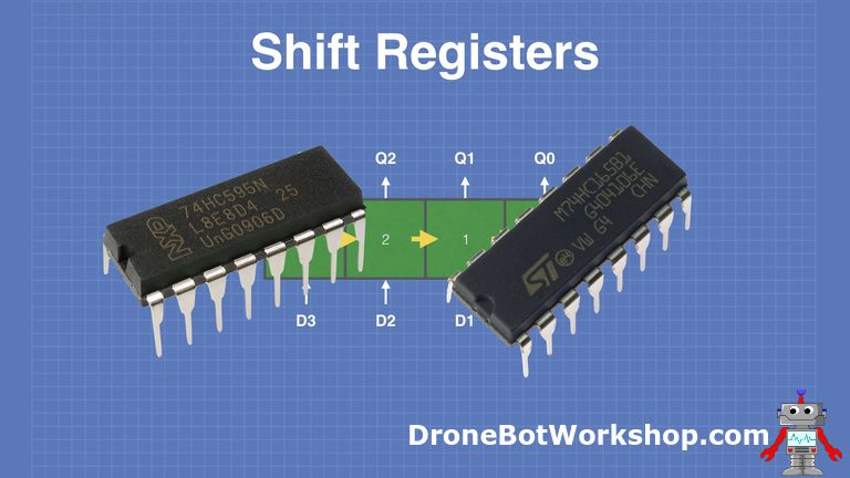
- I start to contemplate the idea of using some faster IC's, like 74HC165 shift registers that @timhoward mentioned already, and most probably more hard to wire in hardware and also much harder to code. Just to have a secondary board. But not 100 I/O pads, just a few, maybe 20 or something. I also remember Teensy board had 40 IO's already and the best one with 58 IO's , which is VERY appealing and also using I2C protocol. Mister @timhoward can confirm it, if is still around.
- Is so disappointing that my Arduino Uno can Not go down under 1ms !!! Ahhhh what a stick in the hearth.
- Also yesterday I received my Arduino Nano board, the replacement for Arduino Uno, and the upgrade for this MCP board I built. I will show some pictures and movie later after I mount everything.
 
To mister @timhoward if you are still around, can you do a test for me? check your maximum fv that you can get from 1 of your I/O from your Teensy board? And dont read it from its datasheet, but do it in reality and tell me if it stops to 1ms like my arduino uno does, or is actually capable to go down to μs(microseconds) ? Thank you !
 
q12 Good morning. To aid help me understand your programming could you slow the scan rate so far that I can see how you select an LED for illumination and post a short video. You can see from my video that I scan the LEDs column by column. In the video I have set the data word for each row as (1111111) so that all 7 LEDs in a column are lit when each of the 5 columns is selected. The data word for the columns follows the sequence (10000), (01000), (00100), (00010), (00001), (10000)......
Thus a sequence of 5 pairs of row and column data words, 10 data words in total, allows me to display any arrangement of LEDs on the display. I want to see what you do.
 
Last edited:
Good morning , where are my manners, right? Hehe.
Remember, this what I do is software programming, but you do it much harder, in hardware !!! Keep this in mind all the time.
Hmmm.... hehe, here is a quick and dirty way of obtaining 1 single led on the matrix, following my already made example.
Just put 5V on pin 3 (with gray) - also dont forget to put resistors !!!! because you will burn the led !!!
and put 0V/ground on pin 11(with gray). Ive also marked with 3red arrows the positions where to put the voltages on which pins.
I will make a more comprehensive explanation for you, but it will take some time, also to make most probably a new drawing, and then the movie and edit it and upload it to yourtube. So until then, at least do this very quick and dirty example here and you will get a procentage of an idea.
1660896916127.png
 
So do you select in software one LED at a time by setting one of the line bits and one of the column bits? And then send this data to the MCP23017? Thus to illuminate say all 35 LEDs you have to sequence through 35 pairs of line and column bits (Column, Line). Each data transfer to the MCP23017 has a cycle time Tc - I have yet to find out what this time is. Thus to refresh completely the 35 LEDs will take a time of 35 x Tc - this is the time necessary to send 35 pairs of (Line, Column) messages. This is a slow way to control the 7 x5 display. You could use the 16 bits data outputs in the format ( C1, C2, C3, C4, C5, X, X, X, L1, L2, L3, L4, L5, L6, L7, X) to illuminate a combination of 7 LEDs in one column using one data transfer, and thus the whole display in 5 data transfers - a considerable reduction in data transfer time from 35 Tc to 5 Tc. (The X means not used).

To do this you would have to add some simple hardware to the 7 x 5 display - some transistors and resistors to interpret the 16 bit data word into switches to control the application of 5V and 0V to the LED array. The scanning has to be done column by column to take advantage of the common cathode arrangement inside the array.

Multiplexing in that way is definitely the best way to do it I would say.
 
So do you select in software one LED at a time by setting one of the line bits and one of the column bits? And then send this data to the MCP23017?
Exactly.
Here is the actual program for 'letter A' that I made and presented in the movie.
You may not understand everything but read the entire program anyway and you will get something out of it. I've also put notes what is line and what is column.
(it was imperative to switch to Input everything after each step, with my custom Reset(); method, otherwise it was liting up the entire next line or column)
Remember a line is HIGH because is +5V and a column is LOW because is 0V. So we lit a single line putting +5V on line01(for ex) and 0v on each desired column.
Code:
#include "Arduino.h"                    //core library that contains all of the Arduino’s built-in functions (from 2022)
#include <Adafruit_MCP23X17.h>          //this is Adafruit-MCP23017-Arduino-Library version 2.1.0
 
Adafruit_MCP23X17 mcp1; //Instantiate mcp1 object
 
void setup()
{
  Serial.begin(19200);
  mcp1.begin_I2C(0x20);
  for(int i = 0; i <= 15; i++)
  {
    mcp1.pinMode(i, INPUT);
  }
  for(int i = 0; i <=15; i++)
  {
    mcp1.digitalWrite(i, LOW);
  }


//LED MATRIX DISPLAY - Single LED - one by one
/*  LOGIC:
//Columns----------------------------------------
//  mcp1.digitalWrite(1, LOW); //A1=1=column A
//  mcp1.digitalWrite(10, LOW);//B1=10=column B

//  mcp1.digitalWrite(3, LOW); //A3=3=column C middle
//  mcp1.digitalWrite(11, LOW);//B2=11=column C middle

//  mcp1.digitalWrite(4, LOW); //A4=4=column D
//  mcp1.digitalWrite(13, LOW);//B6=13=column E

//Lines----------------------------------------
//  mcp1.digitalWrite(5, HIGH);//Line1
//  mcp1.digitalWrite(0, HIGH);//Line2
//  mcp1.digitalWrite(6, HIGH);//Line3

//  mcp1.digitalWrite(2, HIGH);//Line4
//  mcp1.digitalWrite(12, HIGH);//Line4

// mcp1.digitalWrite(8, HIGH);//Line5
//  mcp1.digitalWrite(14, HIGH);//Line6
//  mcp1.digitalWrite(9, HIGH);//Line7
*/

}

void Reset()
{
 for(int i = 0; i <=15; i++)
 {
   mcp1.pinMode(i, INPUT);
   mcp1.digitalWrite(i, LOW);
 }
}


int dly = 1;
void chr_A()
{
  //line1
 mcp1.pinMode(5, OUTPUT);   //line
 mcp1.digitalWrite(5, HIGH);
 mcp1.pinMode(10, OUTPUT);   //column
 mcp1.digitalWrite(10, LOW);
 mcp1.pinMode(3, OUTPUT);   //column
 mcp1.digitalWrite(3, LOW);
 mcp1.pinMode(4, OUTPUT);   //column
 mcp1.digitalWrite(4, LOW);
 delay(dly);
 Reset();
 
  //line2
 mcp1.pinMode(0, OUTPUT);   //line
 mcp1.digitalWrite(0, HIGH);
 mcp1.pinMode(1, OUTPUT);   //column
 mcp1.digitalWrite(1, LOW);
 mcp1.pinMode(13, OUTPUT);   //column
 mcp1.digitalWrite(13, LOW);
 delay(dly);
 Reset();

  //line3
 mcp1.pinMode(6, OUTPUT);   //line
 mcp1.digitalWrite(6, HIGH);
 mcp1.pinMode(1, OUTPUT);   //column
 mcp1.digitalWrite(1, LOW);
 mcp1.pinMode(13, OUTPUT);   //column
 mcp1.digitalWrite(13, LOW);
 delay(dly);
 Reset();

  //line4-midle
 mcp1.pinMode(2, OUTPUT);   //line
 mcp1.digitalWrite(2, HIGH);
 mcp1.pinMode(1, OUTPUT);   //column
 mcp1.digitalWrite(1, LOW);
 mcp1.pinMode(10, OUTPUT);   //column
 mcp1.digitalWrite(10, LOW);
 mcp1.pinMode(3, OUTPUT);   //column
 mcp1.digitalWrite(3, LOW);
 mcp1.pinMode(4, OUTPUT);   //column
 mcp1.digitalWrite(4, LOW);
 mcp1.pinMode(13, OUTPUT);   //column
 mcp1.digitalWrite(13, LOW);
 delay(dly);
 Reset();

  //line5
 mcp1.pinMode(8, OUTPUT);   //line
 mcp1.digitalWrite(8, HIGH);
 mcp1.pinMode(1, OUTPUT);   //column
 mcp1.digitalWrite(1, LOW);
 mcp1.pinMode(13, OUTPUT);   //column
 mcp1.digitalWrite(13, LOW);
 delay(dly);
 Reset();

  //line6
 mcp1.pinMode(14, OUTPUT);   //line
 mcp1.digitalWrite(14, HIGH);
 mcp1.pinMode(1, OUTPUT);   //column
 mcp1.digitalWrite(1, LOW);
 mcp1.pinMode(13, OUTPUT);   //column
 mcp1.digitalWrite(13, LOW);
 delay(dly);
 Reset();

  //line7
 mcp1.pinMode(9, OUTPUT);   //line
 mcp1.digitalWrite(9, HIGH);
 mcp1.pinMode(1, OUTPUT);   //column
 mcp1.digitalWrite(1, LOW);
 mcp1.pinMode(13, OUTPUT);   //column
 mcp1.digitalWrite(13, LOW);
 delay(dly);
 Reset();
 
}


void loop()
{
 chr_A();
}
 
Last edited:

Reply to What is the best signal interface for PC ? in the UK Electrical Forum area at ElectriciansForums.net

OFFICIAL SPONSORS

Electrical Goods - Electrical Tools - Brand Names Electrician Courses Green Electrical Goods PCB Way Electrical Goods - Electrical Tools - Brand Names Pushfit Wire Connectors Electric Underfloor Heating Electrician Courses
These Official Forum Sponsors May Provide Discounts to Regular Forum Members - If you would like to sponsor us then CLICK HERE and post a thread with who you are, and we'll send you some stats etc
This website was designed, optimised and is hosted by untold.media Operating under the name Untold Media since 2001.
Back
Top