B

beara

Hi, we've installed wet UFH throughout a maisonette we've refurbished, and our electrician is querying the connections from the wiring centre to the boiler, as that bit of detail seems to be missing from the attached diagrams. We don't have any radiators; there are 7 UFH loops in 5 rooms, each with their own wired room thermostat. I'm normally pretty good with understanding circuit diagrams and can follow them but I'm struggling a bit with this.

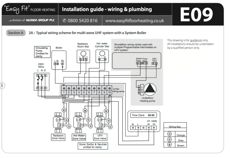
My thoughts are that the wiring centre combines all of the UFH room thermostats and any of them calling for heat sends a signal to the boiler, just like a room thermostat for radiators. On E09 attached I can see how the UFH wiring centre is connected to the boiler wiring centre but I can't see how it turns the boiler on.
To be honest I actually am struggling with the correct question to ask here as I'm confusing myself just looking at the diagrams again, particularly as all of the diagrams refer to s-plan and we've got y-plan.

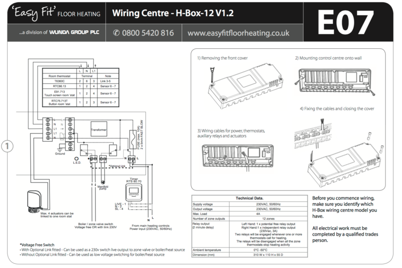
We don't have any radiators so I'm assuming we don't need to connect the radiators room stat? On E07, the bottom of the diagram shows a link to the boiler/zone valve switch and the electrician says that this is just a switch and wouldn't do anything, or I'm not understanding what he's trying to tell me...

Anyway, the bottom line is we don't seem to be able to work out how to finish the wiring to get it all working. Has anybody done a system like this before and can help us please?

Thanks

Jules

Screen Shot 2015-11-03 at 06.44.52.pngScreen Shot 2015-11-03 at 06.44.04.png
 
Hi beara, I too am not sure what you are asking here, the wiring diagrams are pretty straight forward tbh, now for you I can understand they look very confusing as your not an Electrician but your Electrician should be able to interpret these and either adapt to your needs or in more complex systems even add additional controls.

I don't do these systems myself but looking at the plans the only question I would be asking is the UFH control centre says 12zone outputs but the attached diagram E07 only shows what I would desribe as a 1-zone control that can operate up to 4 actuators from a common stat input(assume limited by switching currrent rating)..do you have the actual wiring diagram that comes with the control centre? I would expect multiple stat inputs with their retrospective outputs to the actuators, maybe the diagram has been reduced for simplicity but cannot see how showing extra inputs and outputs is going to confuse anyone.

As for the S plan / Y plan difference that too is a simple solution of using what you would class as the radiator controls for your UFH instead of the extra zone shown on the wiring E09.
 
Last edited by a moderator:
If worked on a few of these systems is the wiring centre close to the underfloor heating manifold? Also there should be a zone valve on the manifold and a pump
 
Hi, we've installed wet UFH throughout a maisonette we've refurbished, and our electrician is querying the connections from the wiring centre to the boiler, as that bit of detail seems to be missing from the attached diagrams. We don't have any radiators; there are 7 UFH loops in 5 rooms, each with their own wired room thermostat. I'm normally pretty good with understanding circuit diagrams and can follow them but I'm struggling a bit with this.

My thoughts are that the wiring centre combines all of the UFH room thermostats and any of them calling for heat sends a signal to the boiler, just like a room thermostat for radiators. On E09 attached I can see how the UFH wiring centre is connected to the boiler wiring centre but I can't see how it turns the boiler on.
To be honest I actually am struggling with the correct question to ask here as I'm confusing myself just looking at the diagrams again, particularly as all of the diagrams refer to s-plan and we've got y-plan.

We don't have any radiators so I'm assuming we don't need to connect the radiators room stat? On E07, the bottom of the diagram shows a link to the boiler/zone valve switch and the electrician says that this is just a switch and wouldn't do anything, or I'm not understanding what he's trying to tell me...

Anyway, the bottom line is we don't seem to be able to work out how to finish the wiring to get it all working. Has anybody done a system like this before and can help us please?

Thanks

Jules

View attachment 30549View attachment 30550

Relay on E07 will switch the white on the 3port valve, orange from 3port valve will trigger the boiler. TBH using a 3port instead of 2X 2ports is a bit backward IMO even though it will work. There is no point following the E09 diagram as you don't have an S-plan +.
 
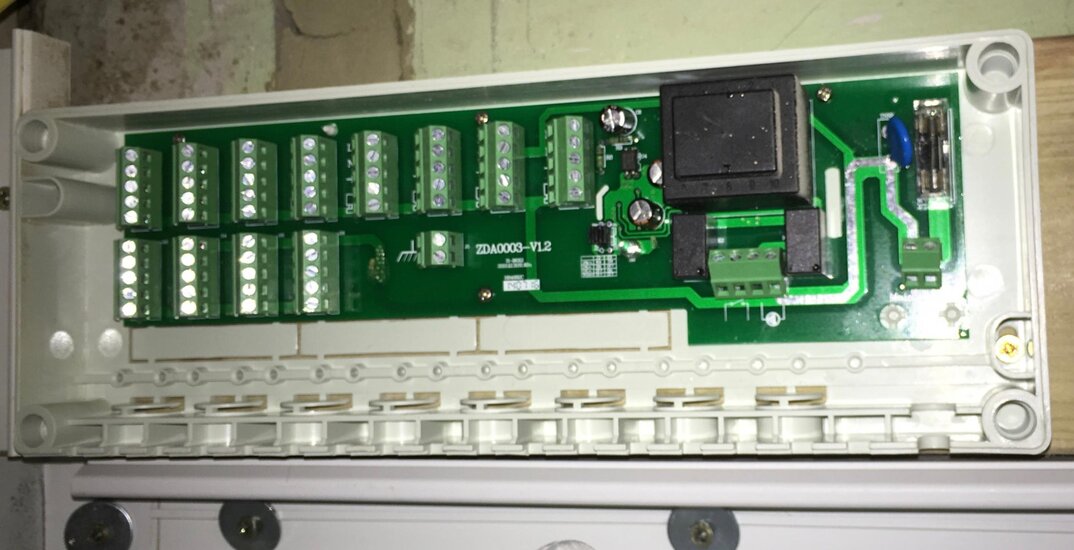
Thanks for all the suggestions, I'll pass that on. I've attached a photo of the wiring centre for info. I'd realised that the wiring diagram on E09 was confusing matters and had been looking at Y plan diagrams to get my head around them. I think the confusion was coming from the fact that on E07, there are two lines drawn away from the boiler relay, when only one seems to be shown on wiring in the wiring centre on E09, but I've found several other plans on t'internet that seem to make it clearer. I'll take this back to him and hopefully it will make sense.

Thank you all for your input :)
 

Attachments

  • IMG_0271.jpg
    IMG_0271.jpg
    240.9 KB · Views: 92
All though there is a timer in the diagram I would not recommend fitting one all the room stats are programmable so the underfloor control centre should just have a permanent feed
 
Thanks for all the suggestions, I'll pass that on. I've attached a photo of the wiring centre for info. I'd realised that the wiring diagram on E09 was confusing matters and had been looking at Y plan diagrams to get my head around them. I think the confusion was coming from the fact that on E07, there are two lines drawn away from the boiler relay, when only one seems to be shown on wiring in the wiring centre on E09, but I've found several other plans on t'internet that seem to make it clearer. I'll take this back to him and hopefully it will make sense.


Thank you all for your input :)

You need to feed one side of the relay so when the relay closes it switches the feed to the white of the valve. The valve will then motor over and close port B of the 3port or go to the mid position depending if the hot water is calling, off or satisfied. As the valve motors in to position it will energise the orange and trigger the boiler.
 
All though there is a timer in the diagram I would not recommend fitting one all the room stats are programmable so the underfloor control centre should just have a permanent feed
It's already been fitted for controlling the hot water. Should it be set to 24hrs on?
 
ll the room stats are programmable, but not sure about the timer - it came with the boiler, so I'll check today.
 

Similar threads

OFFICIAL SPONSORS

Electrical Goods - Electrical Tools - Brand Names Electrician Courses Green Electrical Goods PCB Way Electric Underfloor Heating Electrician Courses Heating 2 Go Electrician Workwear Supplier
These Official Forum Sponsors May Provide Discounts to Regular Forum Members - If you would like to sponsor us then CLICK HERE and post a thread with who you are, and we'll send you some stats etc

Advert

YOUR Unread Posts

Daily, weekly or monthly email

Thread Information

Title
UFH Wiring Centre to boiler
Prefix
N/A
Forum
Central Heating Systems
Start date
Last reply date
Replies
13

Advert

Thread statistics

Created
beara,
Last reply from
beara,
Replies
13
Views
6,505

Advert