HappyHippyDad

~
Esteemed
Arms
Supporter
Dec 18, 2011
5,378
6,731
405,788
Gloucestershire
If you're a qualified, trainee, or retired electrician - Which country is it that your work will be / is / was aimed at?
United Kingdom
What type of forum member are you?
Practising Electrician (Qualified - Domestic or Commercial etc)
I have just completed an EICR.
The install is TT, Ze is 308 ohms.
Zs on all circuits is <1.5 ohm due to bonding.
There is an up front 30mA RCD which trips with the push button but does not trip when tested either at a socket, light or actually in the RCD itself.
I know the RCD is faulty as I had a spare RCBO which I used and tripped as it should.

The lighting circuit had N-E IR readings of 0.27ohms. All other circuits were >2M ohms.

My question is why did the RCBO not trip instantly when I powered up this circuit through the RCBO?
 
-No still confused- Sorry
 
N-E fault. do you mean 0.27 ohms or 0.27 M ohms? either way a N-E fault can stop a RCD from tripping.
 
My initial post may sound a bit confusing as I'm tired!

Put simply, the IR test N-E is 0.27 ohms not M ohms and the RCBO does not trip when the circuit is powered up. It trips as it should do when tested.

Why does it not trip instantly when the circuit is energised with a N-E fault of 0.27ohms?
 
the N-E fault is inhibiting the RCD from tripping. the theory escapes me, but believe me, it's a fact.
 
My kewteck 64 does not trip an rcd on a TT system if the Ze is too high. If it’s over 300 - 400ohms.

This has happened a couple of times.

If I put an additional rod in lowering the Ze it works fine.

Don’t know why.
 
My kewteck 64 does not trip an rcd on a TT system if the Ze is too high. If it’s over 300 - 400ohms.

This has happened a couple of times.

If I put an additional rod in lowering the Ze it works fine.

Don’t know why.
Inhibition of excessive touch voltage.
 
The neutral return even though there is a fault to earth which sounds like a solid connection between the two may not necessarily decide to follow the earth path. It just keeps to the neutral because it is possibly the path of least resistance being a TT system hence no imbalance.
 
Your relatively high 270 thousand ohm resistance of neutral to earth (combined with a high resistance earth return) is sufficiently high enough that there is not enough leakage to earth to imbalance the RCBO in the normal working conditions
 
My kewteck 64 does not trip an rcd on a TT system if the Ze is too high. If it’s over 300 - 400ohms.

This has happened a couple of times.

If I put an additional rod in lowering the Ze it works fine.

Don’t know why.
Yes, but the zs is <1.5ohms.
 
Your relatively high 270 thousand ohm resistance of neutral to earth (combined with a high resistance earth return) is sufficiently high enough that there is not enough leakage to earth to imbalance the RCBO in the normal working conditions
It's 0.27 ohms Des, not 0.27M
 
  • Like
Reactions: Des 56
If you clamp the lighting circuit L+N, what leakage value do you measure?
What's your thinking with this Tony? Just to see if greater than 30mA?
 
.
There is an up front 30mA RCD which trips with the push button but does not trip when tested either at a socket, light or actually in the RCD itself.
I know the RCD is faulty as I had a spare RCBO which I used and tripped as it should.

When you tested at the RCD did you disconnect the outgoing conductors or disconnect L and N of every circuit?

How does the tripping of your spare RCBO prove that this RCD is faulty? Surely all that proves is that you have a working RCBO?
Testing the RCD with all outgoing conductors disconnected proves whether or not the RCD is working.
I didn't disconnect the outgoing conductors. I've seen you have this discussion a few times with others Dave, although I can't remember the outcomes.
If for example I did disconnect the outgoing conductors and the RCD then tested ok would you be happy leaving it in place knowing that at any of the circuits it wil not trip when tested (i.e shows >40ms on x5, >300 on x 1 and >33ma on ramp test). Also, with the above in mind when an RCBO is added to one of the circuits it trips as expected when tested when the RCD in question does not (under exactly the same circumstances).
 
I didn't disconnect the outgoing conductors. I've seen you have this discussion a few times with others Dave, although I can't remember the outcomes.
If for example I did disconnect the outgoing conductors and the RCD then tested ok would you be happy leaving it in place knowing that at any of the circuits it wil not trip when tested

Then how can you know that it is not an outgoing circuit which is causing the RCD to not trip rather than being a faulty RCD.
As the job is an EICR yes I would leave it as it is and code it accordingly, I expect either an FI or C2 code depending on the exact situation on site. The job is to report on the condition of the installation.
If I was testing for any other reason no I wouldn't just leave it as is but I would get to the bottom of the problem and repair or quote to repair as appropriate.
 
Correct me if i'm wrong, but aren't there some models or RCBO that need testing at the output not at the screw? Something to do with where part of the sensing coil is located.

Seem to remember reading about it on here, but have not seen this first hand.
 
Memshield 2 but not the issue here.
 
Correct me if i'm wrong, but aren't there some models or RCBO that need testing at the output not at the screw? Something to do with where part of the sensing coil is located.

Seem to remember reading about it on here, but have not seen this first hand.

Yes, it's the memshield 2 with the site fitted RCBO pod because the coil is in the pod so ends up after the screw terminal.
 
I'll start with an embarrassed face :blush:
Davesparks was right.... again! Damn that man!

Took the outgoing conductors out of the RCD, RCD tests fine. In fact all I needed to do was switch the main switch off of the CU and it tested fine.
As soon as the main switch is switched back on then the RCD will not trip when tested.

I removed the neutral of the circuit with the fault (0.27ohms N-E) from the neutral bar and then the RCD tested as it should even with the main switch on.

Obviously the only reason my RCBO worked on another corcuit was because it wasn't being affected by the N-E fault on the faulty circuit, obvious now!
So..the RCD is fine but the short between N and E is stopping it from functioning when tested.

I shall code accordingly.

However, I do have one last question... Will this RCD still work as it should whilst the fault is there? Do the clients have working fault protection?
 
I'll start with an embarrassed face :blush:
Davesparks was right.... again! Damn that man!

However, I do have one last question... Will this RCD still work as it should whilst the fault is there? Do the clients have working fault protection?

I have been reliably informed by my better half that it is in fact she who is always right, I am either wrong or not listening properly.

The RCD wont provide earth fault protection (well it will for a big enough fault, see my lats paragraph) however it will provide some shock protection.
If you received a shock to true earth the rcd should work, however if you recieved a shock to earthed metalwork I don't think it will work.

Apologies if you know this already but what is happening is that current flowing to earth is diverting via the cpc of the faulty circuit, it then travels via the fault back to the neutral bar and then via the RCD to the supply transformer.

When you established the Zs of 1.5ohms through the bonding how exactly did you test this? If you tested this with the bonding connected to the MET along with all circuits connected then you've more likely measured the return path via the fault than the bonding.

Of course some fault current will still flow to the earth rod in accordance with the rule of resistors in parallel, but as the Zs to Ra ratio is something like 1.5 to 300ish it will take a fair whack of fault current to cause the RCD to trip.
Yes, Zs was tested with bonding connected to MET, so the blasted fault current was just coming back through the neutral due to the fault!

This is what was happening when the RCD was being tested as well. There was no imbalance because the current I produced when testing was coming back through the neutral which was a much more attractive path than the 300ohm rod, again due to the fault! I wonder what Ra would be needed to counteract this!

I do appreciate you explaining that Dave.

Now it's got me thinking more..

Has this happened in this case due to the fault being so bad, i.e 0.27ohm (and in effect joining the earth to the neutral)?
If the IR had been higher, lets say 500ohms or even 6000ohms (both of which should trip an RCD) would the RCD have tripped? I guess we'd have to do some maths, but I expect there would be an exact theoretical IR figure where the RCD would start tripping (depending on the relationship between the Ra of the rod and the degree of severity of the IR fault)?
 
As above, the neutral/Earth fault has desensitised the RCD and therefore the nominally 30mA protection is not being effectively provided.
 
  • Agree
Reactions: static zap
Also, does this mean that on a TT with a poor Ra, if there is a dead short between N-E on one of the circuits, then an up front RCD will never trip when tested (with main switch still on)?
 
Yes, Zs was tested with bonding connected to MET, so the blasted fault current was just coming back through the neutral due to the fault!

This is what was happening when the RCD was being tested as well. There was no imbalance because the current I produced when testing was coming back through the neutral which was a much more attractive path than the 300ohm rod, again due to the fault! I wonder what Ra would be needed to counteract this!

I do appreciate you explaining that Dave.

Now it's got me thinking more..

Has this happened in this case due to the fault being so bad, i.e 0.27ohm (and in effect joining the earth to the neutral)?
If the IR had been higher, lets say 500ohms or even 6000ohms (both of which should trip an RCD) would the RCD have tripped? I guess we'd have to do some maths, but I expect there would be an exact theoretical IR figure where the RCD would start tripping (depending on the relationship between the Ra of the rod and the degree of severity of the IR fault)?

What Ra would be needed to counteract this?
The short answer is that there isn't a value of Ra which could counteract this fault. The fault is a resistance in parallel with the fault, so assuming a theoretical textbook situation rather than the real world:
With the return path of 1.5 ohms via the fault an equal Ra of 1.5ohms the ratio of current flow is 1:1 so a 30mA RCD would need a 60mA fault to trip it.
With an Ra of 0.15 the ratio would be 1:10 so your 30mA RCD would need a 33mA fault to trip it (if my mental maths is working today)
Obviously in the real world RCDs trip at less than 30mA,usually 27ish, so you could in theory get Ra low enough to still have it trip at 30mA,but you'd be looking at an Ra of a fraction of an ohm which is quite tough to achieve without a lot of buried metal.

You can apply a similar answer to your next question.
If the fault was 300ohms and your Ra is 300ohms you would again get the 1:1 ratio. So as the resistance of the fault goes up you will reach a point where its effect becomes negligible on the tripping of the RCD.

With this fault on the system most of the circuits may now appear to have a Zs low enough to allow the mcbs to provide fault protection, apart from the minor issue that all the fault current will be going via the 1mm cpc and neutral of the lighting circuit,provably causing quite a bit of thermal stress.
 
Also, does this mean that on a TT with a poor Ra, if there is a dead short between N-E on one of the circuits, then an up front RCD will never trip when tested (with main switch still on)?

Even on a TT with what is generally accepted as a good Ra this will happen. And it's not just that it won't pass a test, it won't trip on fault.

I think one of the reasons why I object to the 'TTing' of outbuildings without a very good reason is becoming clearer.
And also why I get very annoyed with the 'regs say 200ohms' 'one rod is enough' attitudes towards TT systems.

Dare I raise the subject of SPSN RCBO's at this point?
I was thinking that a little earlier. I've always thought whats all the fuss with 200ohms when 1667 is all that is required. 200 is almost definitely going to be stable enough not to exceed 1667 even with the driest of conditions. However, even though a much smaller Ra (say <20ohms) would still not have been sufficient in my example to enable to RCD to trip, it would in far more cases than 200ohms.
 
I was thinking that a little earlier. I've always thought whats all the fuss with 200ohms when 1667 is all that is required. 200 is almost definitely going to be stable enough not to exceed 1667 even with the driest of conditions. However, even though a much smaller Ra (say <20ohms) would still not have been sufficient in my example to enable to RCD to trip, it would in far more cases than 200ohms.

Yes you can't guard against it 100% as it becomes an endless cycle of 'what if' and 'how many faults can you protect against at once'.

On balance I think I'd rather see a focus on using SPSN RCBO's on all circuits. Your fault would still not trip the RCBO for that circuit, but as soon as another fault occurs it should trip.
 
However, even though a much smaller Ra (say <20ohms) would still not have been sufficient in my example to enable to RCD to trip,

It's actually Zdb that matters for how much the N-E fault affects RCD operation, not the Ra. If there is any low impedance path from the MET, then the current will flow through that just as well as through the actual earth electrode, so a high Ra doesn't inherently mean the RCD is completely disabled. Also important is the resistance of the circuit between the DB and the N-E fault. The higher the resistance, the less the leakage (on other circuits) will divert to the neutral and the less impact the fault will have.

Here is another peculiarity to think about. Shock faults to true earth not involving the CPC, e.g. touching a damaged lawnmower cable standing barefoot in the garden, create a normal unbalanced current in the RCD because in the absence of the CPC there is no parallel path to neutral via the N-E fault. However, the RCD is measuring the algebraic sum of line and neutral current, including leakage in both conductors. This will be made up of the shock current (via the RCD line terminal) and some current from the neutral bar going to earth at the fault (via the RCD neutral terminal). These will tend to be in phase, both flowing through the RCD in the same direction, in which case they will cancel out. The RCD might therefore trip without leakage occurring from the line, or not trip with leakage occurring from the line, or anywhere in between, depending on the magnitudes of the currents.
 
Always good to give an update!

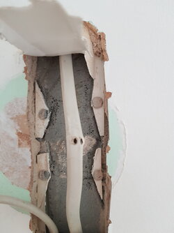
Identified the problem circuit, broke it down in a couple of hours to between 2 points.

It was between a wall switch for a wall light (containing PL and N) and a ceiling pendant. Approx 50cm (DIRECTLY) above the switch was the wall light, with a screw that looked suspiciously directly in line with the PL+N cable. Removed the screw and the fault disappeared! Always feels good doesn't it when you find it, especially when it's a very visible problem that you can show the customer.

Oh yes, and the RCD trips as it should do now when tested. Actually, I better rephrase that otherwise I'll get a few damns from DaveS :D . The RCD always tested fine when tested correctly with all outgoing cables disconnected. It now even tests with them connected :).

cable.jpg

A big thankyou to all those who replied, especially @Lucien Nunes and @davesparks who as usual gave very useful advice.
 
Always good to give an update!

Identified the problem circuit, broke it down in a couple of hours to between 2 points.

It was between a wall switch for a wall light (containing PL and N) and a ceiling pendant. Approx 50cm (DIRECTLY) above the switch was the wall light, with a screw that looked suspiciously directly in line with the PL+N cable. Removed the screw and the fault disappeared! Always feels good doesn't it when you find it, especially when it's a very visible problem that you can show the customer.

Oh yes, and the RCD trips as it should do now when tested. Actually, I better rephrase that otherwise I'll get a few damns from DaveS :D . The RCD always tested fine when tested correctly with all outgoing cables disconnected. It now even tests with them connected :).

View attachment 51925

A big thankyou to all those who replied, especially @Lucien Nunes and @davesparks who as usual gave very useful advice.
Just read all of this topic and this is one of the main reasons why I joined this forum to learn from the more experienced and intelligent sparkys had to read the posts a few times to understand but now I do another tick off the box ?
 

Similar threads

OFFICIAL SPONSORS

Electrical Goods - Electrical Tools - Brand Names Electrician Courses Green Electrical Goods PCB Way Electric Underfloor Heating Electrician Courses Heating 2 Go Electrician Workwear Supplier
These Official Forum Sponsors May Provide Discounts to Regular Forum Members - If you would like to sponsor us then CLICK HERE and post a thread with who you are, and we'll send you some stats etc

Advert

Daily, weekly or monthly email

Thread starter

HappyHippyDad

Esteemed
Arms
Supporter
~
Joined
Location
Gloucestershire
If you're a qualified, trainee, or retired electrician - Which country is it that your work will be / is / was aimed at?
United Kingdom
What type of forum member are you?
Practising Electrician (Qualified - Domestic or Commercial etc)

Thread Information

Title
Why isnt the RCD tripping?
Prefix
N/A
Forum
UK Electrical Forum
Start date
Last reply date
Replies
31

Advert

Thread statistics

Created
HappyHippyDad,
Last reply from
Grant1987,
Replies
31
Views
7,675

Advert