You are using an out of date browser. It may not display this or other websites correctly.
You should upgrade or use an alternative browser.
You should upgrade or use an alternative browser.
PS Electrics
Arms
- Jan 30, 2024
- 241
- 175
- 101,218
- If you're a qualified, trainee, or retired electrician - Which country is it that your work will be / is / was aimed at?
- United Kingdom
- What type of forum member are you?
- Practising Electrician (Qualified - Domestic or Commercial etc)
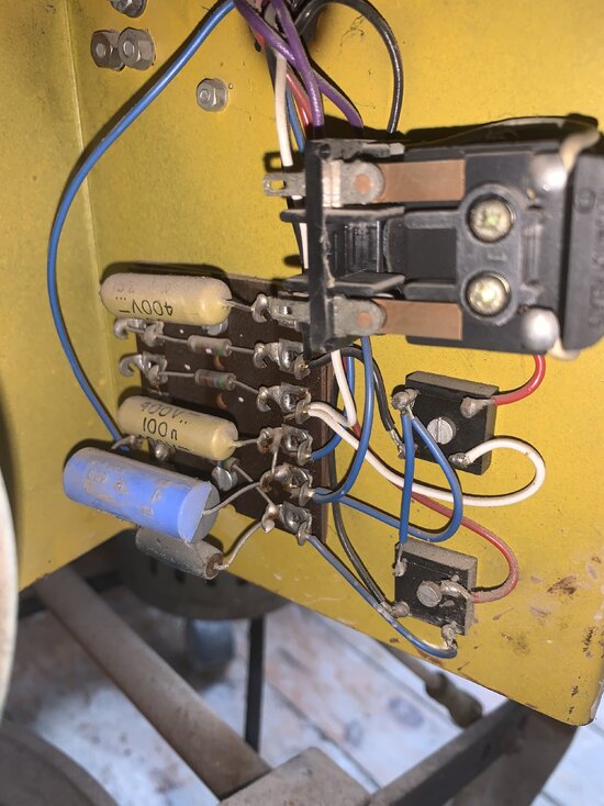
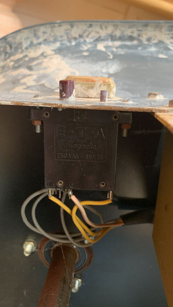
View attachment 123140Hi,
I have an old pottery wheel that i am desperately trying to fix. Does anyone know what any of these parts are/ do ? any help would be really apprecaited.
View attachment 123140Hi,
I have an old pottery wheel that i am desperately trying to fix. Does anyone know what any of these parts are/ do ? any help would be really apprecaited.
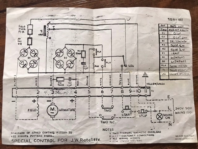
This might be of use?
Hi !! Yes I have been referring to the same diagram … it’s pretty similar but not Exaclty the same. I was reccomended to put in a 2 amp fuse instead of the desired 1A and it fried one of the brown striped (I assume resistor) type components. Do you think best to replace them ?
PS Electrics
Arms
- Jan 30, 2024
- 241
- 175
- 101,218
- If you're a qualified, trainee, or retired electrician - Which country is it that your work will be / is / was aimed at?
- United Kingdom
- What type of forum member are you?
- Practising Electrician (Qualified - Domestic or Commercial etc)
Hi !! Yes I have been referring to the same diagram … it’s pretty similar but not Exaclty the same. I was reccomended to put in a 2 amp fuse instead of the desired 1A and it fried one of the brown striped (I assume resistor) type components. Do you think best to replace them ?
Never put in a higher rated fuse. You need to do some checking to see if there is an underlying problem which caused the fuse to blow. Obviously you have to replace the fried component as well.
PS Electrics
Arms
- Jan 30, 2024
- 241
- 175
- 101,218
- If you're a qualified, trainee, or retired electrician - Which country is it that your work will be / is / was aimed at?
- United Kingdom
- What type of forum member are you?
- Practising Electrician (Qualified - Domestic or Commercial etc)
Hi !! Yes I have been referring to the same diagram … it’s pretty similar but not Exaclty the same. I was reccomended to put in a 2 amp fuse instead of the desired 1A and it fried one of the brown striped (I assume resistor) type components. Do you think best to replace them ?
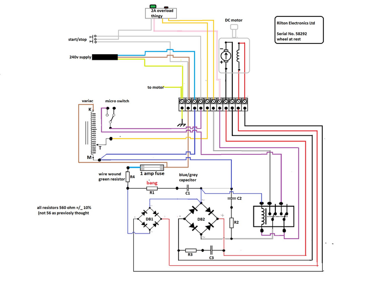
Someone said theirs was slightly different and recreated it in paint, interestingly looks like R1 went bang!
I am not on facebook so could only pull the picture, there might be more info there
It was originally posted here
Here is the link to the facebook image
Log in to Facebook
Log in to Facebook to start sharing and connecting with your friends, family and people you know.
 www.facebook.com
PS Electrics
Arms
- Jan 30, 2024
- 241
- 175
- 101,218
- If you're a qualified, trainee, or retired electrician - Which country is it that your work will be / is / was aimed at?
- United Kingdom
- What type of forum member are you?
- Practising Electrician (Qualified - Domestic or Commercial etc)
To answer your original questionView attachment 123140Hi,
I have an old pottery wheel that i am desperately trying to fix. Does anyone know what any of these parts are/ do ? any help would be really apprecaited.
All of the Resistors and Capacitors from those diagrams are on the circuit board to the left of your picture
To the right is D1 and D2 the two bridge rectifiers
- Jul 15, 2016
- 23,287
- 1
- 29,145
- 315,788
- If you're a qualified, trainee, or retired electrician - Which country is it that your work will be / is / was aimed at?
- United Kingdom
- What type of forum member are you?
- Electrical Engineer (Qualified)
Thankyou for all your help !
Hae ordered solder remover tape and am going t unsolder the wiring to get a closer look at the board, and replace the fried resistor. Also ordered some correct 1 A fuses. Oce ive got the board off and ill post a picture for any help regarding how much resistance i should get my raplcement component for. Will update in a few days!
Hae ordered solder remover tape and am going t unsolder the wiring to get a closer look at the board, and replace the fried resistor. Also ordered some correct 1 A fuses. Oce ive got the board off and ill post a picture for any help regarding how much resistance i should get my raplcement component for. Will update in a few days!
- Jun 29, 2019
- 2,276
- 2,219
- 391,788
- If you're a qualified, trainee, or retired electrician - Which country is it that your work will be / is / was aimed at?
- United Kingdom
- What type of forum member are you?
- Other
- If other, please explain
- Retired Electrical / Electronics Engineer, latterly Quality & Regulatory.
Using the nomenclature in post #5, if it is R1 that has gone bang, I would suspect C1 is faulty (s/c?) as R1 and C1 are in series across the mains, presumably as a filter/suppressor. You might take C1 out of circuit (the blue/grey one) and see if that stops the fuse blowing!
Last edited:
PS Electrics
Arms
- Jan 30, 2024
- 241
- 175
- 101,218
- If you're a qualified, trainee, or retired electrician - Which country is it that your work will be / is / was aimed at?
- United Kingdom
- What type of forum member are you?
- Practising Electrician (Qualified - Domestic or Commercial etc)
Thankyou for all your help !
Hae ordered solder remover tape and am going t unsolder the wiring to get a closer look at the board, and replace the fried resistor. Also ordered some correct 1 A fuses. Oce ive got the board off and ill post a picture for any help regarding how much resistance i should get my raplcement component for. Will update in a few days!
According to the 2nd diagram all resistors are 560 Ohm +/- 10%
This is backed up by the picture you posted of the resistors we can see
Green Blue Black Silver on the visible resistor
Resistor Calculator
This resistor calculator converts the ohm value and tolerance based on resistor color codes and determines the resistances of resistors in parallel or series.
560 Ohm +/- 10%
But double check the actual component if it is not damaged and you can still read the colours since the first diagram shows a different resistance in the table provided for R1.
I believe R1 is the resistor at the bottom of the picture we can't see properly.
Hello !
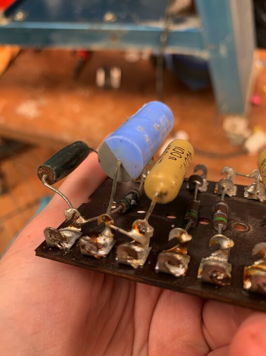
I have now de soldered the board and managed to get it off the wheel. going forward i have a few questions...
During the de soldering process, will the wiring be faulty when i re wire it if some of the rubber housing has melted in places?
furthermore, i am attempting to take off the fried resistor (i have confirmed it is R1) and the wire is wrapped round the port and then soldered on. I have been using desoldering wick but still cant get it off- any reccomendations / would it be fine to cut the fried resistor off with wire cutters?
Also , the resistors have different sizes and positionings of the stripes on them, does this indicate that they all have different resistance. The next step i will do is try and order a replacement resistor and maybe (as reccomended above)another capacitor (although not sure which type).
As always.. any help is very much apprecaited !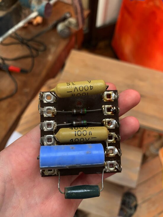


- Jul 15, 2016
- 23,287
- 1
- 29,145
- 315,788
- If you're a qualified, trainee, or retired electrician - Which country is it that your work will be / is / was aimed at?
- United Kingdom
- What type of forum member are you?
- Electrical Engineer (Qualified)
Yes you can cut it and work the wrapped bits off. If you keep it hot enough you should be able to work them off with long nose pliers. Be careful as melted solder can flick up into your face.
- Jun 29, 2019
- 2,276
- 2,219
- 391,788
- If you're a qualified, trainee, or retired electrician - Which country is it that your work will be / is / was aimed at?
- United Kingdom
- What type of forum member are you?
- Other
- If other, please explain
- Retired Electrical / Electronics Engineer, latterly Quality & Regulatory.
I suggest replacing the burnt resistor and the blue/grey capacitor (which I suspect is faulty and the cause of the resistor failing) with a single component rated for the job. This just needs to connect between the bottom two right-hand tags on the board (in the upper pic with your hand!)
Example from Digikey, but you can find such elsewhere. 470 ohms is a satisfactory alternative to the 560 you have
 www.digikey.co.uk
I think it's essential not to put that blue grey capacitor back, unless it is tested and found to be sound at mains voltage. It is not essential to the function of the machine, other than for suppressing interference, so you could leave both R1 and C1 off the board for the moment and check if the machine works when you put it all back.
Example from Digikey, but you can find such elsewhere. 470 ohms is a satisfactory alternative to the 560 you have
PMR209MC6100M470R30 | DigiKey Electronics
Order today, ships today. PMR209MC6100M470R30 – RC EMI Filter 1st Order Low Pass 1 Channel R = 470Ohms, C = 0.1µF Radial from KEMET. Pricing and Availability on millions of electronic components from Digi-Key Electronics.
I think it's essential not to put that blue grey capacitor back, unless it is tested and found to be sound at mains voltage. It is not essential to the function of the machine, other than for suppressing interference, so you could leave both R1 and C1 off the board for the moment and check if the machine works when you put it all back.
so to be clear , i will remove the blue/ grey capacitor and fried resistor .. order the attached filter, and solder it from the bottom right tag (with the green resistor) to the tag directly above where the blue one used to sit?I suggest replacing the burnt resistor and the blue/grey capacitor (which I suspect is faulty and the cause of the resistor failing) with a single component rated for the job. This just needs to connect between the bottom two right-hand tags on the board (in the upper pic with your hand!)
Example from Digikey, but you can find such elsewhere. 470 ohms is a satisfactory alternative to the 560 you have
PMR209MC6100M470R30 | DigiKey Electronics
Order today, ships today. PMR209MC6100M470R30 – RC EMI Filter 1st Order Low Pass 1 Channel R = 470Ohms, C = 0.1µF Radial from KEMET. Pricing and Availability on millions of electronic components from Digi-Key Electronics.www.digikey.co.uk
I think it's essential not to put that blue grey capacitor back, unless it is tested and found to be sound at mains voltage. It is not essential to the function of the machine, other than for suppressing interference, so you could leave both R1 and C1 off the board for the moment and check if the machine works when you put it all back.
After , wire it back up again and test...
PS Electrics
Arms
- Jan 30, 2024
- 241
- 175
- 101,218
- If you're a qualified, trainee, or retired electrician - Which country is it that your work will be / is / was aimed at?
- United Kingdom
- What type of forum member are you?
- Practising Electrician (Qualified - Domestic or Commercial etc)
Hello !
I have now de soldered the board and managed to get it off the wheel. going forward i have a few questions...
During the de soldering process, will the wiring be faulty when i re wire it if some of the rubber housing has melted in places?
furthermore, i am attempting to take off the fried resistor (i have confirmed it is R1) and the wire is wrapped round the port and then soldered on. I have been using desoldering wick but still cant get it off- any reccomendations / would it be fine to cut the fried resistor off with wire cutters?
Also , the resistors have different sizes and positionings of the stripes on them, does this indicate that they all have different resistance. The next step i will do is try and order a replacement resistor and maybe (as reccomended above)another capacitor (although not sure which type).
Different size would be different wattage of resistor. The larger the resistor the higher the wattage.
It is the order and number of colour bands that is important but not their position with respect to other resistors if that is what you mean.
As always.. any help is very much apprecaited !View attachment 123183View attachment 123184
Hello !
I have now de soldered the board and managed to get it off the wheel. going forward i have a few questions...
During the de soldering process, will the wiring be faulty when i re wire it if some of the rubber housing has melted in places?
furthermore, i am attempting to take off the fried resistor (i have confirmed it is R1) and the wire is wrapped round the port and then soldered on. I have been using desoldering wick but still cant get it off- any reccomendations / would it be fine to cut the fried resistor off with wire cutters?
Also , the resistors have different sizes and positionings of the stripes on them, does this indicate that they all have different resistance. The next step i will do is try and order a replacement resistor and maybe (as reccomended above)another capacitor (although not sure which type).
As always.. any help is very much apprecaited !View attachment 123183View attachment 123184
- Jun 29, 2019
- 2,276
- 2,219
- 391,788
- If you're a qualified, trainee, or retired electrician - Which country is it that your work will be / is / was aimed at?
- United Kingdom
- What type of forum member are you?
- Other
- If other, please explain
- Retired Electrical / Electronics Engineer, latterly Quality & Regulatory.
Absolutely correct.so to be clear , i will remove the blue/ grey capacitor and fried resistor .. order the attached filter, and solder it from the bottom right tag (with the green resistor) to the tag directly above where the blue one used to sit?
After , wire it back up again and test...
if you feel inclined, you could put it all back together without the filter, having removed that capacitor and resistor, and check if the motor runs. The absence of the filter won't affect basic operation.
With a new 1A fuse of course.
My hope is that it will spring into life !
so , i replacd the capacitor with a newer one and resistor with a metal film resistor (680 ohms). Fired it up.. i suppose good news as nothing actually fried up this time, but the machine was still unresponsive and nothing started with power. Did some live voltage tests and noticed a significant drop around this first resistor (R4) so have removed it and will try a replacement.
Does anyone know the power and resistance on it- i am not sure which number is which as the Watt sign is inside the Ohms sign. ?
Will try and soure a suitable replacement roday and then test
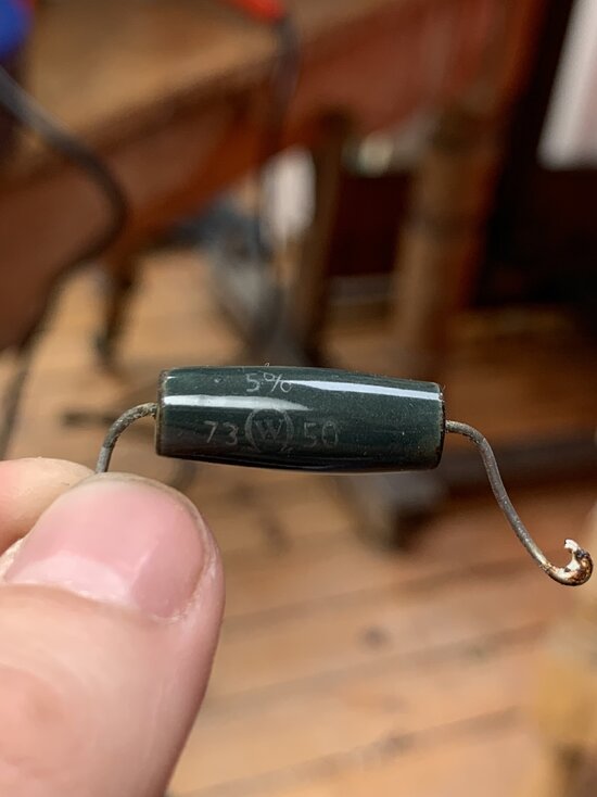
Does anyone know the power and resistance on it- i am not sure which number is which as the Watt sign is inside the Ohms sign. ?
Will try and soure a suitable replacement roday and then test

- Jun 29, 2019
- 2,276
- 2,219
- 391,788
- If you're a qualified, trainee, or retired electrician - Which country is it that your work will be / is / was aimed at?
- United Kingdom
- What type of forum member are you?
- Other
- If other, please explain
- Retired Electrical / Electronics Engineer, latterly Quality & Regulatory.
I think the letter 'W' within the omega symbol is the trademark of the manufacturer - Welwyn Components as they are known.so , i replacd the capacitor with a newer one and resistor with a metal film resistor (680 ohms). Fired it up.. i suppose good news as nothing actually fried up this time, but the machine was still unresponsive and nothing started with power. Did some live voltage tests and noticed a significant drop around this first resistor (R4) so have removed it and will try a replacement.
Does anyone know the power and resistance on it- i am not sure which number is which as the Watt sign is inside the Ohms sign. ?
Will try and soure a suitable replacement roday and then test
View attachment 123231
It's quite a high wattage wirewound resistor, and it's important to replace it with something of equivalent power handling capability.
Also, if it's getting hot, which its designed to cope with, it's not burn out, which is the usual failure mode of these, so I suspect a problem elsewhere is causing excessive current to flow through it. I don't think the resistor is the cause of your problem, but just an indicator of it.
Actually - thinking about this - How hot is it? Is it smoking or actually glowing!? Some heat is to be expected, as that's why they chose that type!
Is there anything marked on the other side of the resistor that we can't see in the photo?
The first circuit diagram posted shows it to be 5.1 ohms, but doesn't give the power rating. Not sure if we can assume yours is the same.
Do you have a multimeter - Edit: I see you have - are there volts at the motor stator winding, and at the Variac?
Replacing components is not really the way to go - you need to find out what's not working - does the relay/contactor click in response to button pushes?
And there's a microswitch apparently associated with the variac speed control that needs to be closed for things to happen - does that click, or more to the point, are there volts there?
Last edited:
I do have a multimeter - i tested the volatage in the blue wire (just bfore R4 ) and it was at 241v but across the resistor and before the resistor was 0.084v. To be honest the on button still makes no noise when pressed (which it used to) but i have tested and got positive beeps for continuity from the start/stop buttons wiring. didnt really notice anything wrong with it heats wise, just that when i was following the track the values dramatically changed when i got to R4 on the multimetre. I suspected that the 2 amp fuse which blew R1 might have caused some damage to R4 aswell so thought best to replace all three components that the current passed through. Lastly, when i check R4 for its resistance it shows 04.6 ohms. I thought this seemed too low compared to my other resistor readings which have been between 600 - 800 ohms .
Ill do some relay research now, as indeed i have not considered this to be a potnential problem !
Ill do some relay research now, as indeed i have not considered this to be a potnential problem !
- Jun 29, 2019
- 2,276
- 2,219
- 391,788
- If you're a qualified, trainee, or retired electrician - Which country is it that your work will be / is / was aimed at?
- United Kingdom
- What type of forum member are you?
- Other
- If other, please explain
- Retired Electrical / Electronics Engineer, latterly Quality & Regulatory.
I don't think there is anything wrong with R4, and your measurement of 4.6 ohms is close enough to the 5.1 in the early circuit diagram. (Note - R4 is in series with the mains in, and is there I suspect as a 'surge limiter', it needs to be very low resistance , unlike the others that are filters across the mains)
Looking at the redrawn circuit, when you apply power, even when the motor is not running, current flows through R4 to the left hand bridge rectifier, and then onto the motor stator winding. So the motor is 'magnetised' but with no current in the armature it's not turning.
So R4 is getting hot supplying the motor stator current.
Then for the motor to run, the interlock circuit needs to come into action, and with the Variac turned up a bit, a voltage will be applied to the right hand bridge rectifier and hence to the motor armature, and it should run.
It would be worth checking the DC voltages coming out of each of the bridge rectifiers.
The one on the left should be rectified mains eg 240V DC, and the one on the right depending on the Variac setting. I imagine you don't have volts coming out of that side.
You need to be very careful making measurements on live equipment. Best to attach probes with power off and then switch on, keeping hands clear, to obtain a reading!
Last edited:
Thankyou , that is all very helpful . Although now i am very puzzled-changed the resistor back to the original green wire wound one, and cant get a reading for 240 volts (which i had previously got) anywhere in the circuit, even at the first connection from the live wire. all my readings are in the 10-30 volt range... so maybe not enough power ? i figured this as was trying to measure for DC on the bridge rectifiers and the reading was zero. not sure what the next step would be from here ?
- Jun 29, 2019
- 2,276
- 2,219
- 391,788
- If you're a qualified, trainee, or retired electrician - Which country is it that your work will be / is / was aimed at?
- United Kingdom
- What type of forum member are you?
- Other
- If other, please explain
- Retired Electrical / Electronics Engineer, latterly Quality & Regulatory.
Has the fuse gone?Thankyou , that is all very helpful . Although now i am very puzzled-changed the resistor back to the original green wire wound one, and cant get a reading for 240 volts (which i had previously got) anywhere in the circuit, even at the first connection from the live wire. all my readings are in the 10-30 volt range... so maybe not enough power ? i figured this as was trying to measure for DC on the bridge rectifiers and the reading was zero. not sure what the next step would be from here ?
Can you logically follow the wiring from mains live coming in to the machine, to the fuse, then to the far end of the green resistor that you've put back?
If it looks visually OK you might try your meter on low ohms range and check from the mains plug live pin continuity to fuse, resistor, bridge rectifier, etc.
There is a danger in swapping components and prodding around that you disturb latent issues and end up worse off!
You need to devise a plan, based on the circuit, of what to check, and follow that through.
We can't remotely fault find, only guess I'm afraid. Interlock/startup circuitry can be puzzling, so I think you'll need to get your head round how that works
 .
.I'm hoping you know the motor works, as success rather hinges on the condition of that!
Pretty sure the motor works - intially the wheel had probelms without starting and then when i gave it a little push i think would get overloaded and the motor would spin much too fast. Seemed in good order, and i thought it more a speed control issue in the wiring. Once i took the circuit board down thats when the whole thing stopped responding. ive marked on this new circuit diagram all the wires where the voltage was around 20v and all the non-coloured wires had a good reading of around 240v (turns out i was using the multimeter wrong).
It makes me think there might be faults with the relay or the '2A overload thingy'... unless the voltgae values are supposed to differ across the circuit?
Also , have eventually found a difference between the wiring diagram and the wiring of my wheel ! The relay i have only has two purple wires connecting it - i cant find any 3rd probe with another purple attached to it.
All immensely helpful ! so thankyou
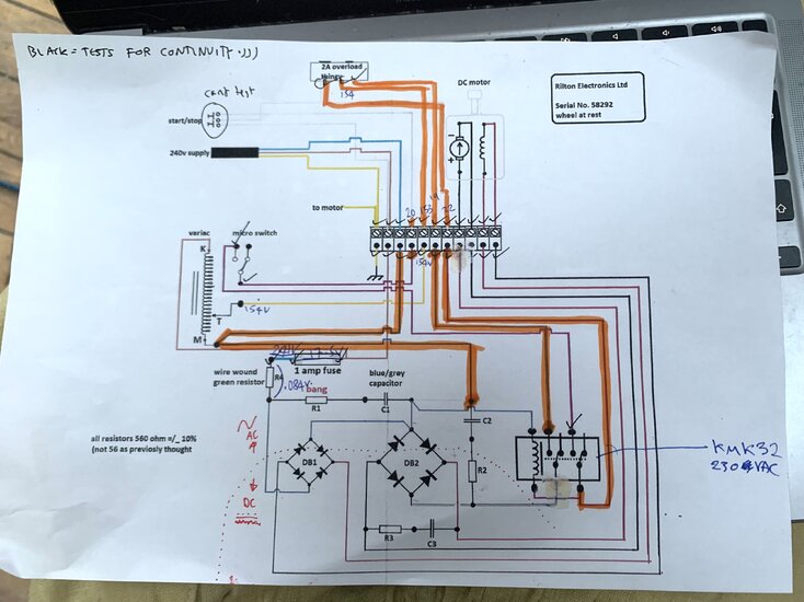


- Jun 29, 2019
- 2,276
- 2,219
- 391,788
- If you're a qualified, trainee, or retired electrician - Which country is it that your work will be / is / was aimed at?
- United Kingdom
- What type of forum member are you?
- Other
- If other, please explain
- Retired Electrical / Electronics Engineer, latterly Quality & Regulatory.
Thank you for the update. Good work!
Could you clarify what you are measuring voltages relative to - is it 'earth', eg the incoming mains earth which is presumably connected to the chassis of the machine as shown by the diagram.
If you are measuring wrt. Earth, I don't understand why your Neutral supply is showing 20V above ground. Am I misunderstand what you are saying? Is that the case just within this machine, or does it apply to your house supply??
154V on the slider of the Variac is a good sign, and this should go up and down as you turn the knob.
But it should exit the 2A overload thingy - is there a reset button on that, or is it self resetting?
Hi , yes ! the black probe was attached to the earth wire on the chasis of the machine and the red probe took all the readings in the various places. I also shouldve been clearer in my above message - the highlighted wires are where readings where around 20v or less - have just rechecked the nuetral and the reading was in the decimal places (so fine). Actually .. now that you say it , as its the nuetral i am thinking that the blue wiring to and from the variac actually SHOULD be no voltage ?
The 2 amp overload (below) does have two buttons on it - the left button im pretty sure is reset, and the right button pops out the left. I reset it and the volatges flowing out where all much higher ! (so i expect no the cause). The start/stop buttons are wired into a plug that i cant seem to open probably with out breaking the case for the switch, but 240v was flowing in to the switch and the grey wire (4th terminal along) only reading 20v. The switch also used to make a sound when pressed and now there is nothing ... maybe i should take that apart ?
The 2 amp overload (below) does have two buttons on it - the left button im pretty sure is reset, and the right button pops out the left. I reset it and the volatges flowing out where all much higher ! (so i expect no the cause). The start/stop buttons are wired into a plug that i cant seem to open probably with out breaking the case for the switch, but 240v was flowing in to the switch and the grey wire (4th terminal along) only reading 20v. The switch also used to make a sound when pressed and now there is nothing ... maybe i should take that apart ?
- Jun 29, 2019
- 2,276
- 2,219
- 391,788
- If you're a qualified, trainee, or retired electrician - Which country is it that your work will be / is / was aimed at?
- United Kingdom
- What type of forum member are you?
- Other
- If other, please explain
- Retired Electrical / Electronics Engineer, latterly Quality & Regulatory.
Correct. The blue wires at the bridge rectifiers are mains neutral.Actually .. now that you say it , as its the nuetral i am thinking that the blue wiring to and from the variac actually SHOULD be no voltage ?
You say the mains is going to the start/stop buttons, but doesn't appear on its output. That could be part of, or the whole, problem. If the start/stop switch put mains on it's middle wire (which goes to the left hand tag of the overload thing), if the overload thing then output that on the adjacent terminal on the diagram, that then connects to terminal 7 (from the left) of the strip, which then goes to the relay coil, it would energise the relay which would switch on the motor.The 2 amp overload (below) does have two buttons on it - the left button im pretty sure is reset, and the right button pops out the left. I reset it and the volatges flowing out where all much higher ! (so i expect no the cause). The start/stop buttons are wired into a plug that i cant seem to open probably with out breaking the case for the switch, but 240v was flowing in to the switch and the grey wire (4th terminal along) only reading 20v. The switch also used to make a sound when pressed and now there is nothing ... maybe i should take that apart ?
So rather than trying to get into the start/stop buttons themselves, can you get at the end of its wires in the machine, take the wire from terminal 2 (mainsL) and the wire on the overload thing, and check continuity between them when you press the start button? See if you can make sense of which start/stop button connects which wire to what!
P.S. Are the grey wires behind the overload thing in the pic, those from the start/stop buttons? One grey going to a tag on the overload thing and the other two to the terminal block?
Last edited:
Similar threads
- Replies
- 2
- Views
- 396
- Replies
- 1
- Views
- 276
- Replies
- 6
- Views
- 266
- Replies
- 4
- Views
- 285
- Replies
- 4
- Views
- 294
- Replies
- 1
- Views
- 239
- Replies
- 15
- Views
- 427
- Replies
- 25
- Views
- 1K
- Replies
- 2
- Views
- 170
- Replies
- 0
- Views
- 147
- Question
- Replies
- 2
- Views
- 176
OFFICIAL SPONSORS


These Official Forum Sponsors May Provide Discounts to Regular Forum Members - If you would like to sponsor us then CLICK HERE and post a thread with who you are, and we'll send you some stats etc


