Jan 23, 2023
12
0
31
Manchester
If you're a qualified, trainee, or retired electrician - Which country is it that your work will be / is / was aimed at?
United Kingdom
What type of forum member are you?
DIY or Homeowner (Perhaps seeking pro advice, or an electrician)
Hi

First post and I'm a DIY-er so apologies if this is the wrong forum to start with.

I have a project at the moment that involves replacing a consumer unit. I've arranged for a proper inspection and certification down the line but in the mean time I have made a start on getting the circuits wired in where I can.

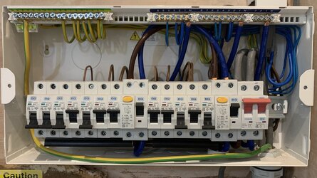
This is where I'm up to so far:
Inside.jpg


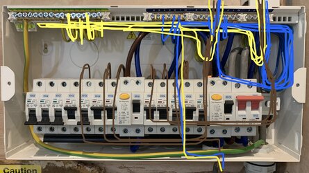
and this shows better how the wiring is routed:
Routing.jpg


I know some of the sheathing on the incoming cables is probably a bit long, but they may move so I've kept a bit of excess. Likewise the neutral and earths are looped as shown to maintain some excess.

The question I have is, is there anything particularly wrong with that routing?

I wasn't sure if it was best for the cables coming from the top to drop straight down and the ones from the bottom to go straight up, or if they should be routed along the bottom and up the sides, e.g. the single one there at the moment, would the earth be better going all the way to the left along the bottom and then up the left hand side, and the live and neutral the same but to the right?

Oh, last thing - this is the bigger picture:
Installation.jpg


I've added an isolator, looking at it now I think the meter tails should probably be shortened a bit, or at least clipped out the way.

Any advice guys, or anything else that stands out that needs resolving?

Thanks...
 

Attachments

  • Inside.jpg
    Inside.jpg
    702.4 KB · Views: 305
  • Routing.jpg
    Routing.jpg
    644.9 KB · Views: 219
How did you isolate the power to fit that isolator.
Can you show a clearer picture of the RCDs.
 
Hi

First post and I'm a DIY-er so apologies if this is the wrong forum to start with.

I have a project at the moment that involves replacing a consumer unit. I've arranged for a proper inspection and certification down the line but in the mean time I have made a start on getting the circuits wired in where I can.

This is where I'm up to so far:
View attachment 105829

and this shows better how the wiring is routed:
View attachment 105830


I know some of the sheathing on the incoming cables is probably a bit long, but they may move so I've kept a bit of excess. Likewise the neutral and earths are looped as shown to maintain some excess.

The question I have is, is there anything particularly wrong with that routing?

I wasn't sure if it was best for the cables coming from the top to drop straight down and the ones from the bottom to go straight up, or if they should be routed along the bottom and up the sides, e.g. the single one there at the moment, would the earth be better going all the way to the left along the bottom and then up the left hand side, and the live and neutral the same but to the right?

Oh, last thing - this is the bigger picture:
View attachment 105831

I've added an isolator, looking at it now I think the meter tails should probably be shortened a bit, or at least clipped out the way.

Any advice guys, or anything else that stands out that needs resolving?

Thanks...
Leaving the single insulated cables that long isn't really achieving anything, personally I would shorten them and not bunch them behind the din rail.

The tails could do with being clipped up.

Why not a rcbo CU ?
Did you work live on installing the isolator ?

What is the size of your main fuse ?

Edit : Westwood Posted above as I was typing
 
Last edited:
First of all, welcome to the forum.

However…

No SPD, they look to be 63A type AC RCD’s, looks to have single 2.5mm cables going into 32A MCB’s

surely this is a wind up?

I can’t see a sparky signing it off and you getting an LABC compliance certificate.
 
The isolation was by removing the main fuse, which I am aware should really have been performed by the DNO.


Is this what you wanted, or each of the banks?

RCDs.jpg


The circuit plan is:
IMG_7659.jpg
 
Leaving the single insulated cables that long isn't really achieving anything, personally I would shorten them and not bunch them behind the din rail.

The tails could do with being clipped up.

Why not a rcbo CU ?
Did you work live on installing the isolator ?

What is the size of your main fuse ?

Edit : Westwood Posted above as I was typing

The choice of not using RCBOs came down to cost. The person paying the bill didn't have the budget.

The isolator was fitted with the main fuse removed, which from memory is 60A I think. The CU main switch is 100A rated, so is the new isolator.
 
If your main fuse is above 63 amps then the rcds are under rated.
 
  • Agree
Reactions: brianmoooore
You have removed the service head fuse and are actually undertaking these works for someone else with no electrical competence.
 
My most immediate concern....(of several)
Does this:
1675283979935.png


lead to this:
1675283997123.png


as your diagram seems to imply?
 
Have you actually rewired this property.
 
First of all, welcome to the forum.

However…

No SPD, they look to be 63A type AC RCD’s, looks to have single 2.5mm cables going into 32A MCB’s

surely this is a wind up?

I can’t see a sparky signing it off and you getting an LABC compliance certificate.
They're type A RCDs.
The single cable is one side of what will be a ring when completed.

My most immediate concern....(of several)
Does this:
View attachment 105842

lead to this:
View attachment 105843

as your diagram seems to imply?
It does, that cable is one end of the kitchen socket ring. The other end of the ring that's also connected to that MCB comes in from the top of the CU.
 
It does, that cable is one end of the kitchen socket ring. The other end of the ring that's also connected to that MCB comes in from the top of the CU.
It's highly dangerous to have a coil of live cable on the floor with bare ends. Final circuits shouldn't be connected up until they are complete and tested.

Also, the other B32 MCB on the left shouldn't have a single 2.5 sq mm cable either as it isn't rated to carry 32 amps. (as mentioned higher up)
 
  • Like
Reactions: JBW175
Wheres your spd?
How much of a gap is there around the cables that enter the top of the cu through that gromit?
Where is the support for the tails (and other cables)?
Wheres your label on the MET?
Why is there a live coil of cable on the floor?
Whos doing notification to labc?
Why is there a 32A mcb serving a 2.5mm radial for 1st floor sockets?
Wheres your test results obtained prior to energising?
 
I expect the 2.5 radial is still looping around the house live until it returns to the CU to complete the ring.
 
Although it appears neat, there are a lot of mistakes would need rectified to meet regulation.
 
  • Like
Reactions: suffolkspark
Is the 32 amp 2.5mm radial feeding a socket or sockets ?
 
It's highly dangerous to have a coil of live cable on the floor with bare ends. Final circuits shouldn't be connected up until they are complete and tested.

Also, the other B32 MCB on the left shouldn't have a single 2.5 sq mm cable either as it isn't rated to carry 32 amps. (as mentioned higher up)

No, that's not the same cable. There are 2 cables coming up through the floor. The coiled cable on the floor is the start of a separate ring and is not connected up or in any way live.

Taken on board the point about the 32A MCB, I was already intending to replace it with the spare 16A.
 
Are you rewiring this property.
 
The first thing to do is to switch off those mcbs one at a time, then turn off the CU main switch followed by the isolator.
Then check the main fuse rating if above 63 amp, disconnect the entire CU and take it back to screw fix.
 

Similar threads

OFFICIAL SPONSORS

Electrical Goods - Electrical Tools - Brand Names Electrician Courses Green Electrical Goods PCB Way Electric Underfloor Heating Electrician Courses Heating 2 Go Electrician Workwear Supplier
These Official Forum Sponsors May Provide Discounts to Regular Forum Members - If you would like to sponsor us then CLICK HERE and post a thread with who you are, and we'll send you some stats etc

Advert

Daily, weekly or monthly email

Thread starter

Joined
Location
Manchester
If you're a qualified, trainee, or retired electrician - Which country is it that your work will be / is / was aimed at?
United Kingdom
What type of forum member are you?
DIY or Homeowner (Perhaps seeking pro advice, or an electrician)

Thread Information

Title
Cable routing inside a consumer unit
Prefix
N/A
Forum
UK Electrical Forum
Start date
Last reply date
Replies
50

Advert

Thread statistics

Created
Andy Hames,
Last reply from
westward10,
Replies
50
Views
10,440

Advert