Discuss cooker hood extractor, old and new wiring colours in the DIY Electrical Advice area at ElectriciansForums.net

dazzad

DIY
Reaction score
2
i am replacing my cooker extractor motor, the old unit has red, white, grey, blue wires,, the new has red, white brown, black, please help, both are 3 speed,, is there a set order for numbers 1, 2 and 3 speeds, in regards to the wire colour.
thanks dazza
 
Any instructions, diagrams or drawings come with new motor?
 
Any instructions, diagrams or drawings come with new motor?
no nothing, i guess you get what you pay for,
i didnt know if there was a industry standard, for the old colours, ie white, =speed 1, grey Speed 2, etc
 
IF the old motor is still electrically intact, you may be able to get some idea by taking and comparing DC resistance measurements of both motors.
 
Any instructions, diagrams or drawings come with new motor?
IF the old motor is still electrically intact, you may be able to get some idea by taking and comparing DC resistance measurements of both motors.
sounds like a plan, thank you, on the off chance i mess up, will it still work, but just with the wrong speeds not coinciding with the correct numbered button?
 
There's only four wires, so it looks like there's no external capacitor involved to complicate matters.
One of the supply wires will almost certainly go direct to the motor and the other three to the switch. As long as you get the one direct to the motor correct, you shouldn't do any harm.
 
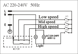
Referring to the random example circuit below, the neutral goes direct to the motor, typically blue (for your old motor?), and may be black on the new motor? (but don't know for sure)

Would be worth checking with a multimeter that you get similar increments of resistance from black to each of the other colours, and from this you could establish the order they go in (low, med, high).
If from black you get two similar resistance readings from different colours, black is not the neutral end, and you need to find which colour is!

There is a risk that if you don't get the right wire for the direct feed (N in the example), the fusible link won't always be in circuit, so you wouldn't have thermal protection of the motor, which could be a safety issue?
F650C44C-40FC-4C98-93B0-4044723893A6.png
 
There's only four wires, so it looks like there's no external capacitor involved to complicate matters.
One of the supply wires will almost certainly go direct to the motor and the other three to the switch. As long as you get the one direct to the motor correct, you shouldn't do any harm.
Brian your a star cheers mate
 
Referring to the random example circuit below, the neutral goes direct to the motor, typically blue (for your old motor?), and may be black on the new motor? (but don't know for sure)

Would be worth checking with a multimeter that you get similar increments of resistance from black to each of the other colours, and from this you could establish the order they go in (low, med, high).
If from black you get two similar resistance readings from different colours, black is not the neutral end, and you need to find which colour is!

There is a risk that if you don't get the right wire for the direct feed (N in the example), the fusible link won't always be in circuit, so you wouldn't have thermal protection of the motor, which could be a safety issue?
View attachment 93809
Thats great thank you very much Avo Mk8, i should be all good now thanks,
thanks to everybody for your help. i feel less bewildered now, 👍
 
  • Like
Reactions: DPG
Referring to the random example circuit below, the neutral goes direct to the motor, typically blue (for your old motor?), and may be black on the new motor? (but don't know for sure)

Would be worth checking with a multimeter that you get similar increments of resistance from black to each of the other colours, and from this you could establish the order they go in (low, med, high).
If from black you get two similar resistance readings from different colours, black is not the neutral end, and you need to find which colour is!

There is a risk that if you don't get the right wire for the direct feed (N in the example), the fusible link won't always be in circuit, so you wouldn't have thermal protection of the motor, which could be a safety issue?
View attachment 93809
right mate, ive found some info out, from the manufacturers, which has totally, duped me lol,
so the original wiring is:- white speed 1, grey speed 2, blue speed 3, and red neutral.
the new motor is :- black speed 1, white speed 2 brown speed 3, and red is neutral./ light
so me only being an Aerospace engineer, thought, 1 to1, 2to2, 3 to 3 and red to red,..... however only speed 3 works,, but by putting brown to any original wires, i can get either 1,2 or 3 switch working, but still on speed 3, 🤔, the new motor is the same size, universal, fitting,
so now im lost, any ideas?
 
Last edited by a moderator:
You need to measure all combinations of DC resistance between the four wires. That's 6 readings in total.
Same for the old motor, if it isn't burnt out.
Post them on here.
 
i am replacing my cooker extractor motor,
What is the make and model number of the cooker hood you are repairing?
Perhaps we can find the correct circuit diagram for it. Or do you have that already?

Either I've misunderstood the original arrangement, you've been given the wrong info, or the new motor is different (eg doesn't have the capacitor on board etc.)

Edit - I've just had a thought - are you checking the motor on its own without the fan installed on it?
There's obviously still a problem with the wiring, but the fact it's always at speed 3 may be due to there being no load on it:
Without a mechanical load, the rotor may not be inclined to 'slip' in relation to the mains frequency, so you may not see any difference in behaviour between the switch settings. I may be wrong with this - maybe someone here can advise?

When the connections are sorted so that each switch makes the motor run, it would be worth seeing what speed it runs at with the motor properly installed driving the fan blades.
Or if that is difficult, lash up some sort of friction device on the shaft of the motor to give it a mechanical load, and see if the switch settings then behave as they should.
 
Last edited:

Reply to cooker hood extractor, old and new wiring colours in the DIY Electrical Advice area at ElectriciansForums.net

Similar Threads

Hello everyone, hope all are well. I'm changing a ceiling rose and have lost the diagram showing where everything was connected (to the old light)...
Replies
8
Views
904
Wouldn't normally note this as an observation on a report but feel I need to. The way the building has been wired is all circuits on L1 have been...
Replies
6
Views
977
Hi, I'm trying to rewire an old plug. I've rewired a few in my time, but all have been with the post-2006 wire colours. I have this old welder...
Replies
3
Views
824
Hi I am looking for some help. My Rangemaster cooker hood stopped working sometime ago, I’ve stripped the hood down and degreased the hood. Ive...
Replies
2
Views
1K
Trying to install a Lutron Toggle/Dimmer (TGCL-153PR) Confused, as the current switch has 3 wires gong to it Black, White, and Red (there is also...
Replies
1
Views
603

OFFICIAL SPONSORS

Electrical Goods - Electrical Tools - Brand Names Electrician Courses Green Electrical Goods PCB Way Electrical Goods - Electrical Tools - Brand Names Pushfit Wire Connectors Electric Underfloor Heating Electrician Courses
These Official Forum Sponsors May Provide Discounts to Regular Forum Members - If you would like to sponsor us then CLICK HERE and post a thread with who you are, and we'll send you some stats etc
This website was designed, optimised and is hosted by Untold Media. Operating under the name Untold Media since 2001.
Back
Top
AdBlock Detected

We get it, advertisements are annoying!

Sure, ad-blocking software does a great job at blocking ads, but it also blocks useful features of our website. For the best site experience please disable your AdBlocker.

I've Disabled AdBlock