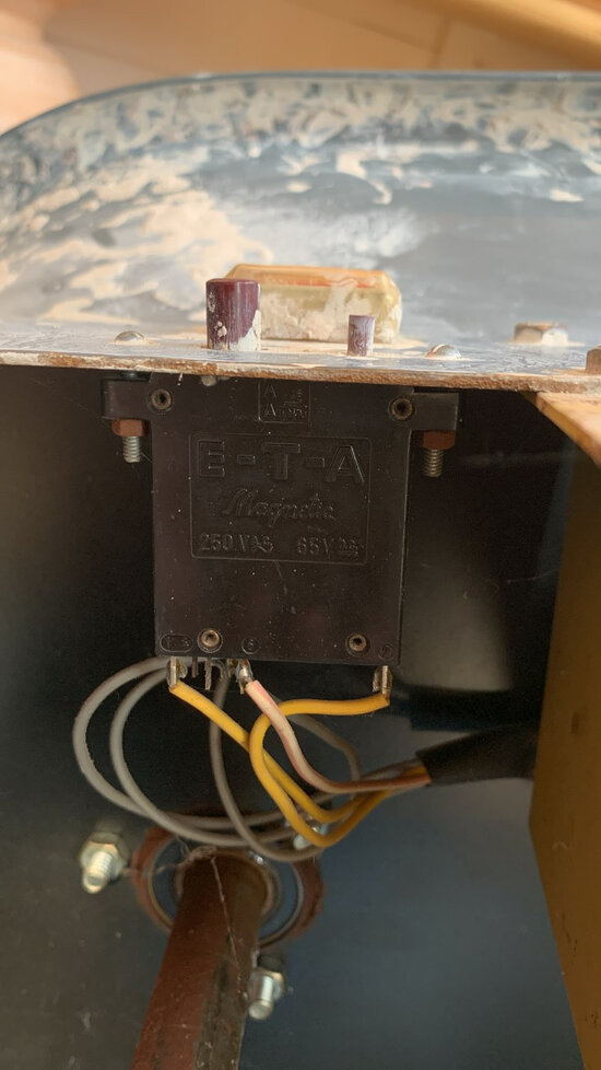
Thankyou , that is all very helpful . Although now i am very puzzled-changed the resistor back to the original green wire wound one, and cant get a reading for 240 volts (which i had previously got) anywhere in the circuit, even at the first connection from the live wire. all my readings are in the 10-30 volt range... so maybe not enough power ? i figured this as was trying to measure for DC on the bridge rectifiers and the reading was zero. not sure what the next step would be from here ?
You are using an out of date browser. It may not display this or other websites correctly.
You should upgrade or use an alternative browser.
You should upgrade or use an alternative browser.
- Jun 29, 2019
- 2,281
- 2,223
- 391,788
- If you're a qualified, trainee, or retired electrician - Which country is it that your work will be / is / was aimed at?
- United Kingdom
- What type of forum member are you?
- Other
- If other, please explain
- Retired Electrical / Electronics Engineer, latterly Quality & Regulatory.
Has the fuse gone?Thankyou , that is all very helpful . Although now i am very puzzled-changed the resistor back to the original green wire wound one, and cant get a reading for 240 volts (which i had previously got) anywhere in the circuit, even at the first connection from the live wire. all my readings are in the 10-30 volt range... so maybe not enough power ? i figured this as was trying to measure for DC on the bridge rectifiers and the reading was zero. not sure what the next step would be from here ?
Can you logically follow the wiring from mains live coming in to the machine, to the fuse, then to the far end of the green resistor that you've put back?
If it looks visually OK you might try your meter on low ohms range and check from the mains plug live pin continuity to fuse, resistor, bridge rectifier, etc.
There is a danger in swapping components and prodding around that you disturb latent issues and end up worse off!
You need to devise a plan, based on the circuit, of what to check, and follow that through.
We can't remotely fault find, only guess I'm afraid. Interlock/startup circuitry can be puzzling, so I think you'll need to get your head round how that works
 .
.I'm hoping you know the motor works, as success rather hinges on the condition of that!
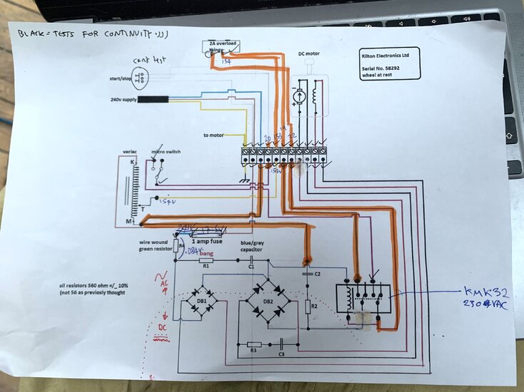
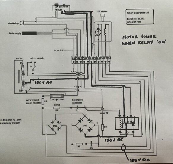
Pretty sure the motor works - intially the wheel had probelms without starting and then when i gave it a little push i think would get overloaded and the motor would spin much too fast. Seemed in good order, and i thought it more a speed control issue in the wiring. Once i took the circuit board down thats when the whole thing stopped responding. ive marked on this new circuit diagram all the wires where the voltage was around 20v and all the non-coloured wires had a good reading of around 240v (turns out i was using the multimeter wrong).
It makes me think there might be faults with the relay or the '2A overload thingy'... unless the voltgae values are supposed to differ across the circuit?
Also , have eventually found a difference between the wiring diagram and the wiring of my wheel ! The relay i have only has two purple wires connecting it - i cant find any 3rd probe with another purple attached to it.
All immensely helpful ! so thankyou


- Jun 29, 2019
- 2,281
- 2,223
- 391,788
- If you're a qualified, trainee, or retired electrician - Which country is it that your work will be / is / was aimed at?
- United Kingdom
- What type of forum member are you?
- Other
- If other, please explain
- Retired Electrical / Electronics Engineer, latterly Quality & Regulatory.
Thank you for the update. Good work!
Could you clarify what you are measuring voltages relative to - is it 'earth', eg the incoming mains earth which is presumably connected to the chassis of the machine as shown by the diagram.
If you are measuring wrt. Earth, I don't understand why your Neutral supply is showing 20V above ground. Am I misunderstand what you are saying? Is that the case just within this machine, or does it apply to your house supply??
154V on the slider of the Variac is a good sign, and this should go up and down as you turn the knob.
But it should exit the 2A overload thingy - is there a reset button on that, or is it self resetting?
Hi , yes ! the black probe was attached to the earth wire on the chasis of the machine and the red probe took all the readings in the various places. I also shouldve been clearer in my above message - the highlighted wires are where readings where around 20v or less - have just rechecked the nuetral and the reading was in the decimal places (so fine). Actually .. now that you say it , as its the nuetral i am thinking that the blue wiring to and from the variac actually SHOULD be no voltage ?
The 2 amp overload (below) does have two buttons on it - the left button im pretty sure is reset, and the right button pops out the left. I reset it and the volatges flowing out where all much higher ! (so i expect no the cause). The start/stop buttons are wired into a plug that i cant seem to open probably with out breaking the case for the switch, but 240v was flowing in to the switch and the grey wire (4th terminal along) only reading 20v. The switch also used to make a sound when pressed and now there is nothing ... maybe i should take that apart ?
The 2 amp overload (below) does have two buttons on it - the left button im pretty sure is reset, and the right button pops out the left. I reset it and the volatges flowing out where all much higher ! (so i expect no the cause). The start/stop buttons are wired into a plug that i cant seem to open probably with out breaking the case for the switch, but 240v was flowing in to the switch and the grey wire (4th terminal along) only reading 20v. The switch also used to make a sound when pressed and now there is nothing ... maybe i should take that apart ?
- Jun 29, 2019
- 2,281
- 2,223
- 391,788
- If you're a qualified, trainee, or retired electrician - Which country is it that your work will be / is / was aimed at?
- United Kingdom
- What type of forum member are you?
- Other
- If other, please explain
- Retired Electrical / Electronics Engineer, latterly Quality & Regulatory.
Correct. The blue wires at the bridge rectifiers are mains neutral.Actually .. now that you say it , as its the nuetral i am thinking that the blue wiring to and from the variac actually SHOULD be no voltage ?
You say the mains is going to the start/stop buttons, but doesn't appear on its output. That could be part of, or the whole, problem. If the start/stop switch put mains on it's middle wire (which goes to the left hand tag of the overload thing), if the overload thing then output that on the adjacent terminal on the diagram, that then connects to terminal 7 (from the left) of the strip, which then goes to the relay coil, it would energise the relay which would switch on the motor.The 2 amp overload (below) does have two buttons on it - the left button im pretty sure is reset, and the right button pops out the left. I reset it and the volatges flowing out where all much higher ! (so i expect no the cause). The start/stop buttons are wired into a plug that i cant seem to open probably with out breaking the case for the switch, but 240v was flowing in to the switch and the grey wire (4th terminal along) only reading 20v. The switch also used to make a sound when pressed and now there is nothing ... maybe i should take that apart ?
So rather than trying to get into the start/stop buttons themselves, can you get at the end of its wires in the machine, take the wire from terminal 2 (mainsL) and the wire on the overload thing, and check continuity between them when you press the start button? See if you can make sense of which start/stop button connects which wire to what!
P.S. Are the grey wires behind the overload thing in the pic, those from the start/stop buttons? One grey going to a tag on the overload thing and the other two to the terminal block?
Last edited:
- Jun 29, 2019
- 2,281
- 2,223
- 391,788
- If you're a qualified, trainee, or retired electrician - Which country is it that your work will be / is / was aimed at?
- United Kingdom
- What type of forum member are you?
- Other
- If other, please explain
- Retired Electrical / Electronics Engineer, latterly Quality & Regulatory.
Hi Ursi
If you are still investigating your potters wheel, I have a suggestion.
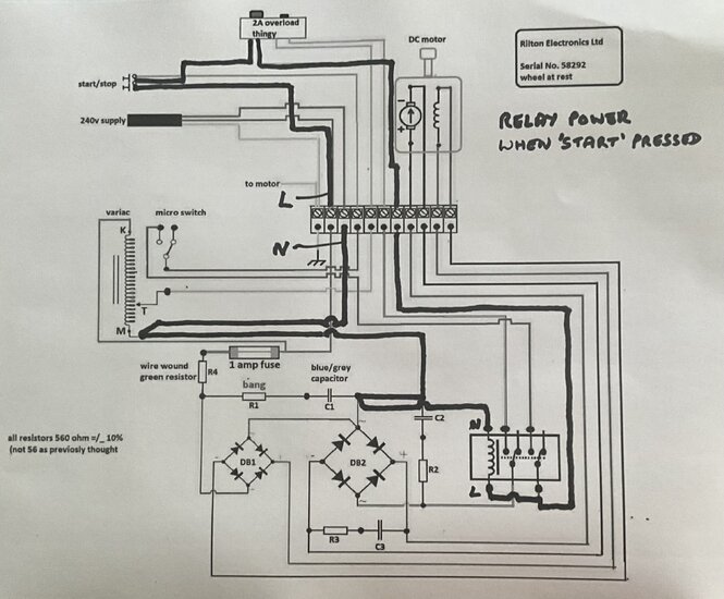
There are two parts of the circuit that both need to be completed for the motor to run. Each is highlighted below.
The first actuates the relay via the start/stop buttons and the overload breaker.
The second powers the motor from the variac and bridge rectifier when the relay above is activated.
I would suggest (with the machine disconnected from power!) you try to trace continuity of the first circuit (upper pic), by taking the grey wire out of terminal block 2 (L), attach that to one probe of your multimeter on ohms, and then work your way to each component round the circuit. Don't get mislead by possible intermediate resistance readings from other parts - you are looking for 'zero' ohms! And if not there, you may have found a fault. Of course you (should) have the relay coil resistance once you get to the mains Neutral side of the relay.
Good luck!
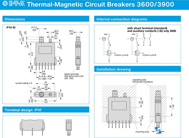
I haven't managed to find a schematic of the old thermo magnetic breaker, but a current not-quite-equivalent is shown below, which makes some sense of which pin number does what!


Last edited:
Hi Avo.. just taken a look and wow thankyou very much as that all looks so helpful! i am away for the next few days so will do the continuity tests soon as im back. Ill have a go at taking off the grey wire - so you say if i dont hear continuity beeps at any point or find a point in the circuit where it reads some resistance it might indicate fault?
The diagrams and ETA breaker manual look great so thankyou - they are also helping me make sense of which wires actually connect to which.
I also found another pic, which might be useful in terms of navigating the wiring from the start / stop to the breaker. (although blurry, they are both in the backround of the pic). Ill give it a go at desoldering brown and grey from terminal 2 when im back.
Report back soon with more...
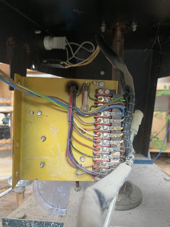

- Jun 29, 2019
- 2,281
- 2,223
- 391,788
- If you're a qualified, trainee, or retired electrician - Which country is it that your work will be / is / was aimed at?
- United Kingdom
- What type of forum member are you?
- Other
- If other, please explain
- Retired Electrical / Electronics Engineer, latterly Quality & Regulatory.
Thank you for the extra pic. Very useful!
I suggested 'taking the grey wire off' but seeing the construction I don't want you to unnecessarily desolder or cut any wires.
If you were to loosen all the screws holding that tagstrip/ loom in place, and pull the tagstrip out from under the screws and leave it hanging in free space, using the mains L wire gives the grey wire connection you need for continuity checks, so you can at least trace mains L from the plug to the start/stop buttons, then to the breaker. If that's all OK you'll need to put the tagstrip back and tighten the screws to do further measurements. Good luck!
PS: And yes, when you don't get a continuity beep, that indicates the thing you're checking the output of is faulty (or not switched on!)
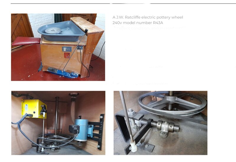
PPS: is it (a bit!) like this:

Last edited:
Amazing - shall do when back, although am wondering why it would be useful to take the tag strip off to do the continuity checks? i am able to get to each of the wires without it coming off, and naturally when i measure voltage at tag 2 the grey was at 240v as its connected to the brown.
Found a very similar wheel to mine aswell - left an excessively long link below ! altough not that useful as not many pics of the inside... and yes, the general layout is the same as the other ratcliffe wheel you sent .

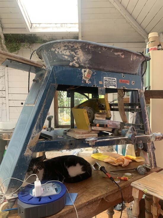
Heres a non zoomed in pic aswell. If you zoom on the second you can see on the back of the yellow chasis , the micor switch and pedal mechanism , that closes the switch when the pedal is pressed.
(mind the cat hahah)
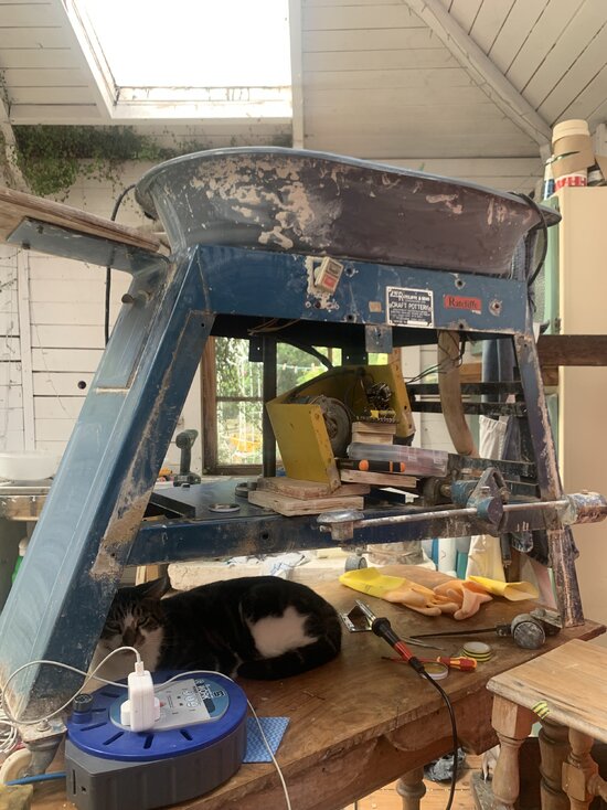
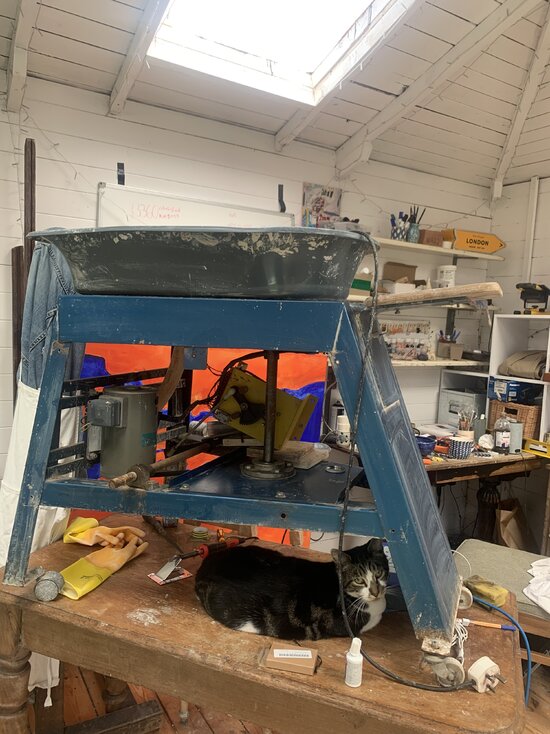
Found a very similar wheel to mine aswell - left an excessively long link below ! altough not that useful as not many pics of the inside... and yes, the general layout is the same as the other ratcliffe wheel you sent .

Fully Reconditioned JW Ratcliffe And Sons Electric Pottery Wheel/ Belt driven | eBay UK
It is a full sized studio electric potter wheel, which is driven by a 0.33hp DC motor and belt driven. A belt driven wheel is much lighter than a cone driven wheel. Your foot does not take the whole weight of the motor in the foot pedal operation.
www.ebay.co.uk
Heres a non zoomed in pic aswell. If you zoom on the second you can see on the back of the yellow chasis , the micor switch and pedal mechanism , that closes the switch when the pedal is pressed.
(mind the cat hahah)


Attachments
- Jun 29, 2019
- 2,281
- 2,223
- 391,788
- If you're a qualified, trainee, or retired electrician - Which country is it that your work will be / is / was aimed at?
- United Kingdom
- What type of forum member are you?
- Other
- If other, please explain
- Retired Electrical / Electronics Engineer, latterly Quality & Regulatory.
ThanksAmazing - shall do when back, although am wondering why it would be useful to take the tag strip off to do the continuity checks? i am able to get to each of the wires without it coming off, and naturally when i measure voltage at tag 2 the grey was at 240v as its connected to the brown.
Found a very similar wheel to mine aswell - left an excessively long link below ! altough not that useful as not many pics of the inside... and yes, the general layout is the same as the other ratcliffe wheel you sent .

Fully Reconditioned JW Ratcliffe And Sons Electric Pottery Wheel/ Belt driven | eBay UK
It is a full sized studio electric potter wheel, which is driven by a 0.33hp DC motor and belt driven. A belt driven wheel is much lighter than a cone driven wheel. Your foot does not take the whole weight of the motor in the foot pedal operation.www.ebay.co.uk
Heres a non zoomed in pic aswell. If you zoom on the second you can see on the back of the yellow chasis , the micor switch and pedal mechanism , that closes the switch when the pedal is pressed.
(mind the cat hahah)
View attachment 123320
View attachment 123319
Just quickly - the reason I suggested removing the tag strip is that on that terminal there's also a wire to the fuse and thereby to other components, so (without actually working it out) I thought you might come across continuity by another route when probing, which could confuse any conclusions. Having just written this I realise that just taking the fuse out when doing the checks will be just as effective!!
- Jun 29, 2019
- 2,281
- 2,223
- 391,788
- If you're a qualified, trainee, or retired electrician - Which country is it that your work will be / is / was aimed at?
- United Kingdom
- What type of forum member are you?
- Other
- If other, please explain
- Retired Electrical / Electronics Engineer, latterly Quality & Regulatory.
Apologies for posting again Ursi.
I wanted to say how I think the start/ stop process is supposed to work, as it might help you when it comes to checking it out. I'm assuming the start/stop switch is effectively two independent momentary push-buttons, connected in series (hence three wires) the stop having NC contacts, and the start having NO contacts.
When you push the 'start' button the first circuit I drew up is energised (for as long as you hold in the button) and causes the relay to snap closed. This changes the contacts over from the way they are shown in the circuit, to how I show the contacts in my second diagram. This creates another circuit (that I haven't illustrated) which connects the right hand relay contact (which switches the relay coil) to the micro switch, which when closed connects to the stop switch (which is normally closed) thus feeding mains L to the relay coil as well. So when you release the start button, power continues to be supplied to the relay coil and it holds in. This means the motor gets power as per my second diagram.
Subsequently opening the microswitch or pressing the 'stop' button removes power to the relay and it drops out.
The upshot of this is you're looking for 'start' button continuity for as long as you press it, and the 'stop' button to have continuity, but when pressing it, it goes open circuit.
Similar threads
- Replies
- 2
- Views
- 400
- Replies
- 1
- Views
- 286
- Replies
- 6
- Views
- 267
- Replies
- 4
- Views
- 292
- Replies
- 4
- Views
- 295
- Replies
- 1
- Views
- 239
- Replies
- 15
- Views
- 429
- Replies
- 25
- Views
- 1K
- Replies
- 2
- Views
- 172
- Replies
- 0
- Views
- 149
- Question
- Replies
- 2
- Views
- 189
OFFICIAL SPONSORS


These Official Forum Sponsors May Provide Discounts to Regular Forum Members - If you would like to sponsor us then CLICK HERE and post a thread with who you are, and we'll send you some stats etc
Advert
YOUR Unread Posts
-
DNO, EV installer, house fuse many cables and not a clue
- Latest: brianmoooore
-
-
-
-
-
-
-
-


