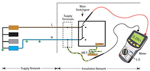
R1 is the resistance of the line conductor from the origin of the installation (service head) to the point of testing.
R2 is the resistance of the circuit protective conductor from the origin of the installation to the point of testing.
An earth fault loop path is the "circuit" consisting of the conductors that will be carrying the fault current when a fault to earth occurs.
Start of supply from transformer, along line, round to the fault and down the circuit protective conductor (earth) back to the transformer.
Z is impedance.
Z e is external (i.e outside the installation)
Z s is system (i.e. the whole of the transformer, supply cable, service head, consumer unit, final circuit.)
R1+R2 can be considered the impednace/ resistance of the part of the earth fault loop within the installation


