R
You are using an out of date browser. It may not display this or other websites correctly.
You should upgrade or use an alternative browser.
You should upgrade or use an alternative browser.
P
PEG
T
Toneyz
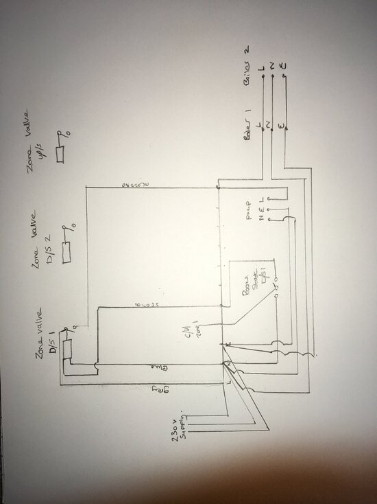
As shown, but need an isolator to each boiler. Assuming that it is switched live, N&E to each boiler.
- Mar 9, 2015
- 2,075
- 2,984
- 4,688
- If you're a qualified, trainee, or retired electrician - Which country is it that your work will be / is / was aimed at?
- United Kingdom
- What type of forum member are you?
- Other
Never a good idea to get advice on an Splan from a Yplan.Are you a qualified sparky?
Separate these zones and the hot water system and draw it out should be easier to get your head round
- Mar 9, 2015
- 2,075
- 2,984
- 4,688
- If you're a qualified, trainee, or retired electrician - Which country is it that your work will be / is / was aimed at?
- United Kingdom
- What type of forum member are you?
- Other
Never come across 2 boilers twinned up? Why would you do this?
Surely it would be better to have a couple of zones of one boiler and a couple of the other.
Surely it would be better to have a couple of zones of one boiler and a couple of the other.
R
Rob brazendale
Two boilers in series. If there’s a Fault with one they still have heating and hot water. They have fitted a low loss header to the system aswell
D
davesparks
Two boilers in series. If there’s a Fault with one they still have heating and hot water. They have fitted a low loss header to the system aswell
You didn't think to.mention the low loss header at the start of the thread then?
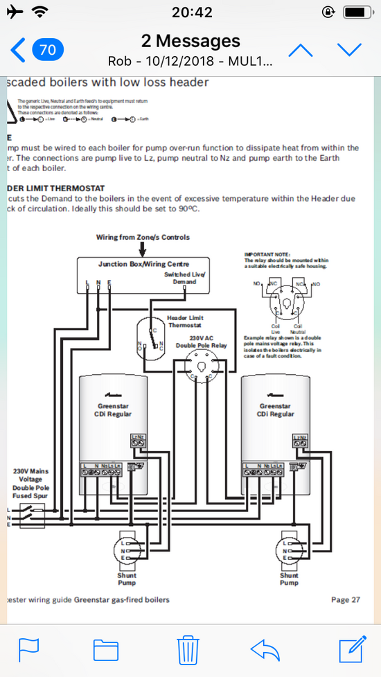
Based on this new information you will almost certainly have a boiler circulating pump which will need to be controlled by both boilers via a relay. This pump circulates water from the boilers into the low loss header.
The second pump will be circulating water from the low loss header and around the CH and DHW zones.
Worcester bosch will send you a wiring diagram of how to connect two of their boilers together if you give their tech support a call. It is important that you do this bit correctly otherwise you may damage the boilers or create a dangerous situation for anyone working on them in the future.
P
PEG
Have a look at boiler sequencers
....I have done...many,many times

This is why i know they are paralleled and not in series.
I did a two line post,hoping to get more detail,and Dave blew us out of the water with his thorough retort

These are systems and features,which are not added "ad-hoc",most generally specced and designed from the get-go. If this is the case,there will be system drawings for both the hydraulic and electrics.
If not,Dave's last paragraph is applicable.
R
Rob brazendale
Hey guys. I got this information off the plumber today, we’ve got 3 wireless programmers, 3 x 2 ports (heating) 1x 2 port for the cylinder,frost stat, 2 x secondary heating pumps (they’re the main system heating flows,stats will control these)2 x primary heating pumps (shunt pumps) cylinder stat, and secondary return hot water pump ,
2 x Worcester 40 cdi classics, 2 x grundfos 25/80 SF pumps, 2x grundfos 15/60 PR pumps, 3x Honeywell 2 port valves (heating) , 1 x Honeywell 2 ports (hot water circ) cylinder stat, frost stat and grundfos gold pump HWSR, #CONTROLS# 3 wireless single channel programmable room thermostats, 1 x wired hot water timer
2 x Worcester 40 cdi classics, 2 x grundfos 25/80 SF pumps, 2x grundfos 15/60 PR pumps, 3x Honeywell 2 port valves (heating) , 1 x Honeywell 2 ports (hot water circ) cylinder stat, frost stat and grundfos gold pump HWSR, #CONTROLS# 3 wireless single channel programmable room thermostats, 1 x wired hot water timer
R
Rob brazendale
L
Leesparkykent
R
Rob brazendale
L
Leesparkykent
Have you got a pipe stat for the header or is there a high limit stat build in?Frost peotection
R
Rob brazendale
R
Rob brazendale
Similar threads
- Replies
- 5
- Views
- 305
- Replies
- 4
- Views
- 639
- Replies
- 13
- Views
- 1K
- Replies
- 1
- Views
- 804
- Replies
- 8
- Views
- 615
- Replies
- 6
- Views
- 507
- Question
- Replies
- 2
- Views
- 329
- Replies
- 31
- Views
- 2K
- Replies
- 4
- Views
- 1K
- Replies
- 9
- Views
- 4K
OFFICIAL SPONSORS


These Official Forum Sponsors May Provide Discounts to Regular Forum Members - If you would like to sponsor us then CLICK HERE and post a thread with who you are, and we'll send you some stats etc
Advert
Thread Information
- Title
- S plan heating system
- Prefix
- N/A
- Replies
- 37


