Discuss Lucien's vintage fairground electrics thread in the UK Electrical Forum area at ElectriciansForums.net

Lucien Nunes

-
Mentor
Esteemed
Arms
Reaction score
13,478
In which we can discuss and reminisce about such wonderful and fascinating subjects as:

  • The origin of the Ward-Leonard speed control system
  • Speedways, octopuses & big wheels
  • Old British trucks
  • Summer evenings, girls & candy floss
  • Orange 2-pin plugs
  • Tungsten light bulbs
  • Mather & Platt dynamos
etc.

A few of my past posts have hinted at an interest in fairgrounds and their people and machines. IRL it's more than skin deep and goes back as far as I can remember.

Before we start: Not all the pleasures that can be had at the fairground are compatible with one another. I wrote the following in a post 8 years ago and it is still important:

.... standing between two of these on the back of an old Scammell ballast tractor, hot and oily after running all day, lighting set throbbing to the beat of 50's R'n'R ....don't do this when at the fairground with your other half. I did, and it was difficult to convince her to share a waltzer car with with someone covered in soot who smells of diesel....
** I have since learned that most girls don't go to the fair to fix injection pumps with their mates **

Hold on tight, keep your arms inside the cars....
 
giphy.gif
 
Mather and Platt. I remember discussing the Manchester Dynamo, years ago. They were used in textile mills around here. Basically Edison's generator, so dc, it was a big development on it for higher output in the cotton mills.
 
I was going to start by posting assorted pics of interesting and historic equipment, but due to having a very rough week with chemo and various other new health issues, I can't get the pics, the scanner and myself all together. In truth I'm finding it difficult to get myself together anyway.

So I am going to fill in by introducing this picture - the terminal box cover used on many Mather and Platt machines - by way of a blueprint held in the collection at the National Fair and Circus Archive.

If you've been to a few steam rallies you will have seen this cover plate - shown bottom right - on the front of the dynamos on various showmans' engines, usually with the details picked out in contrasting paint. But what does it all mean?

It shows four ways of connecting the machine - clockwise generator, anticlock generator, clockwise motor and anticlock motor - according to the purpose for which you want to use it. Obviously once a machine is perched on the steamer's smokebox extension, its role is fairly well carved out as that of a generator, but the fact that they show these options right there on the casting is a reminder that at their heart, DC generators and motors are basically the same thing. Why, then, the different connection options? Does the direction not relate to polarity, as it does on most DC motors that one might play with today?

Who's interested in a bit of DC machine theory, or would you prefer just to wait for some colourful pics?
 
I recall when I came across a ward Leonard setup and we had a convo' on here I think, it takes some getting your head around and hands up to him.
 
The Ward-Leonard system was the 'classic' application of variable-voltage generators as variable-speed DC drives for lifts, industrial plant etc. But another early application of the variable-voltage generator was to drive the huge, heavy scenic railway rides that evolved out of the steam switchback, popular in the 1910-1930 era. For rides like switchbacks that can be significantly out of balance at rest, direct drive by steam is practical because a steam engine can develop full torque at negligible speed and pull away under fine control. The scenics had large multi-seater electrically-driven cars on a track traversing very steep inclines that demanded equally high torque at low speed, but this time an electrical control was needed. In due course I will tell about that, and the special 'scenic' showman's road locos developed for the purpose, but we'll begin tomorrow with a closer look at those Mather and Platt dynamos that were so often at the heart of the system.
 
It's funny really, there we were going along quite happily in life with horse/cart and a barge, and through the power of money mixed with a tiny fraction of steam, inventers went and made every body extremely unhealthy and following a path they laid for there own wealth.
Not the inverters fault though, what they should of done is invented it and kept it to themselves.
That way they could of pulled nothing but there own hair out every time it went wrong.

Sorry, I've gone right off topic.

I'm extremely interested to hear more about the variable speed DC drive for lifts, great post btw.
 
In which we can discuss and reminisce about such wonderful and fascinating subjects as:

  • The origin of the Ward-Leonard speed control system
  • Speedways, octopuses & big wheels
  • Old British trucks
  • Summer evenings, girls & candy floss
  • Orange 2-pin plugs
  • Tungsten light bulbs
  • Mather & Platt dynamos
etc.

A few of my past posts have hinted at an interest in fairgrounds and their people and machines. IRL it's more than skin deep and goes back as far as I can remember.

Before we start: Not all the pleasures that can be had at the fairground are compatible with one another. I wrote the following in a post 8 years ago and it is still important:

.... standing between two of these on the back of an old Scammell ballast tractor, hot and oily after running all day, lighting set throbbing to the beat of 50's R'n'R ....don't do this when at the fairground with your other half. I did, and it was difficult to convince her to share a waltzer car with with someone covered in soot who smells of diesel....
** I have since learned that most girls don't go to the fair to fix injection pumps with their mates **

Hold on tight, keep your arms inside the cars....
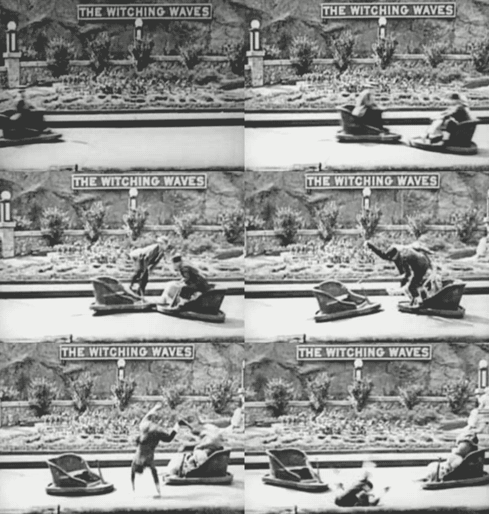
My wife and I went to an amusement park many years ago and rod a ride which spends everyone around all the time. The problem I think that it was going so fast it was mashing everyone against me and I was sitting on the outside next to the rail and I started screaming like crazy to stop the ride. That happened before I came an electrician. Knowing what I know now I’m suspecting that there must have been some kind of VFD which was probably not working and they bypassed it so that big motor was flying. It felt like 3600 RPMS. Is that possible @Lucien Nunes
 
I suppose it depends on how long ago that was, but I must say that I'm not familiar with the normal practice in the US for amusement park power and drives. In the UK, as far as travelling fairs and carnivals are concerned, we have been very traditional. Well into the 1990s and beyond, 110V DC power was standard for everything except the music systems and many of the older rides had electrical equipment dating back 50 years or more. A simple rheostat would serve as a starter for the main motor's armature, examples of which I will soon post. Only really in the last 25 years have we seen widespread use of AC / VFD drives for travelling rides and some still use their original DC motors driven from rectifiers. Permanently-installed theme park rides are more likely to have been AC-driven from new, and technically more up to date. Once I've got a few pics up, you might be able to draw some comparisons between our 'olde-tyme' methods and what you do in the US.

This thread has got off to a slow and picture-less start because I have been mainly in bed trying to sleep off the chemotherapy. It has always been a dream of mine to own an old ballast tractor, perhaps a 1960s Scamell or ERF, with a pair of traditional Showman's generators mounted abreast in the conventional way. It was definitely in the list of top 10 things to do before I die, but it's not looking likely to happen now. I do have a couple of vintage sets and if Edward and I can get one of them to a show next summer and actually make some power with it, and we can sit on the grass sipping a beer listening to the old diesel rumbling gently, no matter what else happens, I will be 100% happy with that.
 
Me i had a dream once taking the grankidds to local amusement arcades
With masks on and dropping the monies in the penny's machines, you know the slidder ones and bumping them to get the dosh out the bloody things are set up like
Big piggy bank with alarm on,
 
Please give context when posting stuff like that! That's a deliberate attempt by young adult riders to abuse a childrens' ride and it's mistitled, so it does seem to have been done for shock effect. I am not sure why the car came adrift, that is concerning, but it's also a bit off-topic here because I want to talk about the electrics of British travelling fairs mainly, and that's a mechanical issue with a ride in Sweden.

The challenge that fairs have to deal with is that when anything goes wrong it generates huge publicity, often because it involves families with children etc. Every accident becomes nearly national news in a way that similar accidents at home do not. The HSE discovered a few years back, by searching records over many years, that people are 12 times more likely to have an accident travelling to and from the fair, than at the fair itself. And that even takes in the 'deliberate accidents' where nutters try to climb out of their ride seats or defeat the safety interlocks etc. If you count only genuine accidents where something is wrong with the ride structure etc, then the ratio is even higher. Accidents caused by mechanical failure of traditional rides are vanishingly rare but very few people post videos that show this fact.

Anyway I was going to start scanning and uploading pics of these lovely old dynamos and things, but I have a new distraction which is that my birthday dinner which we had to cancel has apparently been rearranged for tomorrow and some guests have just messaged me to say they are coming. We need to get cracking with Xmas decs, food prep, all sorts, not least because I'm at the stroke clinic much of tomorrow daytime.

So hold your galloping horses for 24 hours and I'll be round again...
Ok Mr Ferris Wheel, holding our carousel horses 🤣
 
OK off we go, but not with the Mather and Platt dynamos yet because I can't find the pics. We'll start in the middle and just chat and post stuff and see where it goes.

Today, I want to take a first look at ride motors and their speed controls. In the era we're considering, most rides were driven by 110V DC brush motors. Either one big motor driving the centre of a ride such as a galloper, which could be in the range of say 5-20hp, or a number of smaller motors in individual cars such as you might find on a juvenile train ride. These motors differ in detail but almost every motor and indeed generator that we are going to meet at the fair is of the same general configuration: A wound armature fed by brushes on a commutator revolves in a stationary magnetic field.

These days, many DC motors have permanent magnets to create the field but for much of the history of DC motors, there were no permanent magnets strong enough to make an efficient, compact motor, so the magnetic poles on the frame were wound with field coils to form electromagnets. There are various ways the field coils can be connected - in series with the armature, in parallel (shunt) and a combination of the two (compound). We'll begin with shunt winding (see attached diagram) as this is the simplest way to produce a motor that runs at a steady, controllable speed. The field is not necessarily connected directly in parallel with the armature as there can be control resistances in either circuit. What we mean by shunt-wound is that the armature and field are energised separately from the supply voltage, so that their currents are independent and can be controlled separately. Note, this different to most small brush motors in household appliances and power tools, etc, which are series-wound.

Time to introduce some essential characteristics of ideal, generalised DC motors:
  • Torque is proportional to armature current and also proportional to field strength.
  • Speed is proportional to armature voltage but inversely proportional to field strength.

If we want a shunt-wound motor to run at a steady speed and be able to deliver maximum torque if the ride needs it, we must supply it with:
  • Full field current (this is normally limited by the resistance of the field winding itself, and is at maximum when connected directly to the rated supply voltage.)
  • Armature voltage to suit the desired speed. Again, nornally the rated speed of the motor corresponds to the rated voltage across the armature.
  • Whatever current the armature demands, to develop the required torque. The higher the mechanical load, the more current it will take.

Before this post gets too wordy, let's have some pics of drive motors. Here you can see the main motors on an octopus, ferris wheel, dive bomber and speedway ark, and for comparison the small motor on a juvenile ride. In the next post we'll look at the speed controls themselves.
 

Attachments

  • Ark Crompton motor.png
    1.4 MB · Views: 34
  • Ferris wheel motor.png
    526.2 KB · Views: 35
  • Dive bomber motor 1.png
    988.4 KB · Views: 32
  • Octopus motor sm.png
    820.2 KB · Views: 30
  • Small motor juvenile sm.png
    819.2 KB · Views: 32
  • Shunt motor.png
    741.7 KB · Views: 41
I mentioned putting resistance in series with the armature circuit and labelled it 'starting resistance' on the circuit in the previous post. In due course we will need to look in detail at how armature resistance works both as a soft-start and as a speed control. It will serve both functions quite well for most rides, e.g. a twist or chairoplanes can be perfectly well controlled with a resistance. But its shortcomings will start to show when we apply it to the huge, heavy speedway, and an exploration of those shortcomings will lead us to the origins of the Ward-Leonard system and the wonderful 'Scenic Showmans' locos.

At the very elementary level, we can consider that adding resistance to the armature circuit reduces the armature current and therefore the torque, making for a soft start. But how does it control speed? In the next post we will throw some equations at the problem but suffice to say for now, with many kinds of ride, the more resistance, the lower the speed, so we want a variable resistance that can be cut out in steps.

Take a look at these controllers and the circuit diagram. There is usually a cage with resistance elements not unlike spiral heating elements, on which is mounted a faceplate control with studs over which the wiper arm runs. Each stud to the right progressively cuts out the resistance section by section, with the final stud being all out. There is usually a knife switch to the left which serves as both the emergency stop and for inching the ride for loading, while the controller handle remains on whichever stud gives a suitable creeping acceleration for this.

BTW some of these pics are from memorable days out. Resistance Controller 1, for example, is Michael Miller's 12-car big wheel by Eli Bridge (NFCA index BW23) at Barnet with Smith's fair in 1983. When I took the pic of the controller, I was 11 years old and Ottawan's 'Hands Up' was spinning on the turntable. You can see the whole thing in these pics at the NFCA two years earlier and you will see the generator that was powering it, in a later post.


The next post will be heavy with theory!
 

Attachments

  • Resistance controller 1.jpg
    588.3 KB · Views: 27
  • Resistance controller 2.jpg
    651.5 KB · Views: 26
  • Ferris wheel motor and controller.png
    1.4 MB · Views: 25
  • Small resistance.jpg
    457 KB · Views: 27
  • Resistance controller circuit.png
    46.4 KB · Views: 25
Last edited:
As seen in the above pics, resistance control of DC motors is popular, but what are its limitations and how can it be improved? To understand how the motor interacts with the resistance and mechanical load, we need equations. I stated as facts earlier that for an ideal shunt motor at constant field current, speed is proportional to voltage and torque to current. To turn those statements into equations, all we need to do is define a constant of proportionality, which says how many volts per RPM and how many newton-metres per amp that particular machine develops. The constant is more or less a description of the machine in a single figure, that takes into account many factors such as physical dimensions, number of turns of windings etc. We call it the flux constant, kΦ (phi):

ω = Ea / KΦ (Angular velocity (=2.π.RPM) is armature EMF divided by flux constant)
τ = Ia . kΦ (Torque is product of armature current and flux constant)

Ea is the EMF developed in the armature as it spins in the magnetic field. When a machine is running at its no-load speed (ignoring losses) the induced EMF exactly opposed the applied voltage and no current flows, i.e. it is in equilibrium, neither generating nor motoring. Increase the voltage or decrease the speed, and it starts motoring, with current flowing through the armature one way and torque assisting the rotation. Decrease the voltage or increase the speed and it starts generating, with current flowing through the armature the other way and torque opposing the rotation.

If we connect a supply of constant voltage Vs, again ignoring losses and internal resistance:
ω = Vs / KΦ (speed equals supply voltage over flux constant)
and since both the voltage and the flux constant are constant, so is the speed. As we are ignoring the losses, we find that the speed is completely independent of torque. We take some motor or another, connect it to 110V and it runs at 1200RPM. The more torque we demand, the higher the armature current, but the speed remains constant. This is not quite true of a real-world motor but let's assume it is for now in our ideal motor.

But now let us put a resistance R in series with the armature, as per the circuit diagram in the previous post. A voltage Vr will be developed across it, proportional to the current Ia and to its resistance, and this appears as the difference between the supply voltage Vs and the armature EMF Ea.
Vr = R . Ia (voltage across resistance is proportional to armature current)
Ea = Vs - Vr (EMF across armature equals supply voltage minus drop in resistor)
Therefore Ea = Vs - (R . Ia)
Now the armature EMF is no longer independent of its current. Substituting for Ea and Ia:
ω . KΦ = Vs - (R . τ/kΦ)
And likewise the speed is no longer independent of the torque. With constant supply voltage and field current:
For a given torque, the higher the resistance the lower is the speed
For a given resistance, the higher the torque the lower is the speed


So the resistance spoils the constant speed characteristic of our ideal shunt motor. If the load torque varies, so will the speed for a given setting of the rheostat control. In the next episode, we'll see how the nature of the load decides whether that is a problem or not.
 
Before we get into any more theory, here's a little video shot at the Great Dorset in 2018.

We can see and hear the effect of starting a big wheel ride under resistance control, on the steam showmans engine that is generating for it. The engine is Burrell Special Scenic 10NHP, Serial No. 4030 'Dolphin' built 1925. The ride is a 12-car Eli Bridge wheel, NFCA No. BW04 'Atlantic Star', built in Illinois in 1947, owned by Edward Howard.

With the engine running at a steady speed the dynamo is producing 110V DC and the ammeter is sitting at around 110A with the ride stationary, representing a lighting load of about 12kW. The wheel is embarking riders during the video and as each car is loaded it is nudged round to the next one every half a minute or so. As it accelerates, the ammeter swings up to about 170A, i.e. the ride motor is taking about 60A or 6.6kW. This probably translates to about 6hp delivered to the wheel itself. You can hear and see the engine come under load as the reaction torque of the dynamo increases. The canopy lights dim slightly while the engine governor reacts to increase the steam admission and restore the speed and voltage.

Dolphin was one of the very last Special Scenics built by Burrell, with larger LP cylinder bore and 10 NHP rating. Nominal Horsepower (NHP) was an old method of describing the size of a steam engine based on piston speed and bore, but it is not an actual rating of power equivalent to BHP (brake horsepower) or watts. Dolphin is capable of something like 80 BHP mechanical output, which depends as much on the evaporative surface area of the boiler as on the engine. Belted to the engine flywheel is the Mather and Platt main dynamo, I think a model P8C but perhaps not the original one.

Being a Special Scenic engine, Dolphin is also fitted with an auxiliary dynamo on a bracket behind the chimney. You can just catch a glimpse of it in the video, but it is not belted and not in use here. We will return to the subject of how the two dynamo system improved ride starting performance, but it's worth mentioning that the name of the loco 'Dolphin' refers to the original ride that it powered, the Orton and Spooner 'Diving Dolphins' scenic railway ride, which required the special starting arrangements due to the very heavy cars with individual motors starting against unbalanced static forces, unlike the relatively balanced big wheel or a flat ride.

Enjoy!

 
Last edited:

Reply to Lucien's vintage fairground electrics thread in the UK Electrical Forum area at ElectriciansForums.net

OFFICIAL SPONSORS

Electrical Goods - Electrical Tools - Brand Names Electrician Courses Green Electrical Goods PCB Way Electrical Goods - Electrical Tools - Brand Names Pushfit Wire Connectors Electric Underfloor Heating Electrician Courses
These Official Forum Sponsors May Provide Discounts to Regular Forum Members - If you would like to sponsor us then CLICK HERE and post a thread with who you are, and we'll send you some stats etc

Electrical Forum

Welcome to the Electrical Forum at ElectriciansForums.net. The friendliest electrical forum online. General electrical questions and answers can be found in the electrical forum.
This website was designed, optimised and is hosted by Untold Media. Operating under the name Untold Media since 2001.
Back
Top
AdBlock Detected

We get it, advertisements are annoying!

Sure, ad-blocking software does a great job at blocking ads, but it also blocks useful features of our website. For the best site experience please disable your AdBlocker.

I've Disabled AdBlock