P

penamyeahshe

Hello brothers and sisters, I have recently taken on the hobby of electrical wiring as a novice and need some help to figure this out.

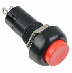
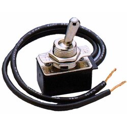
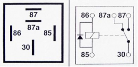
I have trouble understanding and physically wiring on my little wiring table i have. The following are the contents I have: one small light, two push button switches (exactly like the pic), a 5 pin relay (exactly like the pic), a toggle switch to control the flow of electricity from main power supply and a FUSE .

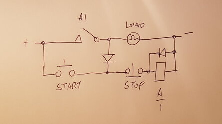
I want it wired so that when I press Switch A the light turns on and when I press Switch B the light would turn off. Using the relay.

Is this possible?

Thank you in advance!!
s-l1000.jpg
 

Attachments

  • s-l1000 (1).jpg
    s-l1000 (1).jpg
    51.5 KB · Views: 34
  • 694dd490-89c7-4c9c-928c-0ed640150d09_1.f326df873978d23a7457ff0f58972c68.jpeg
    694dd490-89c7-4c9c-928c-0ed640150d09_1.f326df873978d23a7457ff0f58972c68.jpeg
    30.3 KB · Views: 39
  • relay_5_pin_electrical_drawing_large.png
    relay_5_pin_electrical_drawing_large.png
    49.2 KB · Views: 38
to control the flow of electricity from main power supply and a FUSE .
You've posted this thread in the Electrical forum, not the Automotive forum and you talk about connecting it to 'the main power supply'.... Do you mean the house electricity supply?

It's a relay meant for DC 12 volts from what I can see. If you do connect that relay to a main electricity supply the best case senario is it will be damaged but more likely it will explode and could cause injury.
 
You talk about connecting it to 'the main power supply'.... Do you mean the house electricity supply?

It's a relay meant for DC 12 volts from what I can see. If you do connect that relay to a main electricity supply the best case senario is it will be damaged but more likely it will explode and could cause injury.
Sorry it’s a small Dc 12 power supply
 
  • Like
Reactions: Marvo
Switch A would need to be N/O and switch N/C but both in the coil supply circuit.
 
Like this.
20201120_214558.jpg


Note, the switches must be rated for the full current of the lamp
 
  • Like
Reactions: penamyeahshe
Note, the switches must be rated for the full current of the lamp
Not necessarily, but would be better with a DPDT relay, the relay contacts would have to be though.
 
Not necessarily, but would be better with a DPDT relay, the relay contacts would have to be though.
With that relay they do have to be rated for the full current.

Agree if you use a different relay, that is a different matter, however the op has specified the relay.

You could use two of that relay type and then you could reduce the current rating of the switches.
 
  • Like
Reactions: penamyeahshe
Hello Julie, Would this wiring be in the case if the switches were momentary switches?
Yes, you don't want switches which remain in a switched position.

So one for example, the stop/off button needs to be normally closed - when you press it it must open the contacts, in which case it will turn the relay off. If it remains open, then no matter how much you press the on button, since this stop button would be signifying stop it would never turn on. (This may be correct for a safety interlock of course).

In the same way, the start/on button must be normally open, and only close when you want it to start/switch on.

If this locks into a continuously on position, then although pushing the stop button will stop/turn off, it would start/go on straight after, just as if you were pushing start all the time.

If you have a very slow relay, and a very fast switch, there is a possibility that an on->off very quickly followed by a return to on might be so quick that although the relay starts to open, the power comes back on before it can physically open.

This is more of an issue with dc relays as these can gain a "magnetic memory" - basically the ironwork of the relay becomes a week permanent magnet, usually not sufficient to remain closed, but enough to slow it down.
 
Re. the start switch having to be rated for the load current or having to use a DP relay. As this is a DC relay it is not necessary if the holding circuit is completed through a diode as per attached, which prevents the switch energising the load directly. Suppression diode also added as per normal practice.
 

Attachments

  • 16068602374653843233077266960512.jpg
    16068602374653843233077266960512.jpg
    35.9 KB · Views: 34

Similar threads

OFFICIAL SPONSORS

Electrical Goods - Electrical Tools - Brand Names Electrician Courses Green Electrical Goods PCB Way Electric Underfloor Heating Electrician Courses Heating 2 Go Electrician Workwear Supplier
These Official Forum Sponsors May Provide Discounts to Regular Forum Members - If you would like to sponsor us then CLICK HERE and post a thread with who you are, and we'll send you some stats etc

Advert

Daily, weekly or monthly email

Thread Information

Title
need help for the schematic diagram and wiring of this configuration.
Prefix
N/A
Forum
UK Electrical Forum
Start date
Last reply date
Replies
13

Advert

Thread statistics

Created
penamyeahshe,
Last reply from
Lucien Nunes,
Replies
13
Views
3,123

Advert