M

Mick duffy

hey everyone,

Wondering if anyone has done there 2391-52 practical exam lately i have mine this week just wondering a few things.

Rcd tests if i have a lighting circuit protected by a 61009 rcbo which point should the test be carried out at the distribution board or the accessory its self as i realise we are trying to reduce Live testing.

We have 2 lots of paperwork electrical installation cert & eicr we have been told that 2 circuits have been rewired which they will go on the eic but with regards to the eicr do we just leave the circuits black we here they have been removed to go onto the new eic cert? It’s a 3 phase Db which a circuit supplies the single phase Db?

Thanks for any help and if this is a stupid question again I apologise thanks
 
The two circuits for the EIC, will also be on the EICR.
You just copy the results on the EIC over to the EICR.

All dead tests will be conducted first.
Then they will energise the board for you to conduct the live tests, Ze PFC and RCD test.

I used the 3 pin plug lead to conduct the RCD test.

Remember to calculate Zs for all circuits after you have measured Ze.

Sorry, can’t recall whether the fault finding is before energisation, or after.
 
RCD test just at the end on one of the sockets with all the covers back in place. That is what I did.

For Zs I just calculated most circuits and I only measured on the circuits with sockets.

More of a safety aspect I guess instead of poking probes in ceiling roses live.
 
  • Agree
Reactions: Diver233
Thanks for the replies will even ask the question prior to starting the exam as the tutor is actual sound thanks
 
You won’t be expected to measure Zs anywhere.
Live working is kept to an absolute minimum.
 
The practical was pretty simple really, Ive rarely done inspection and testing and I thought it was a doddle, as long as you know why you are doing it then can't really go wrong.
 
  • Like
Reactions: Vortigern
I tested continuity of earth conductors, then the RFC conductors. The order of the rest of the tests, went out the window.
 
That’s it all complete PASSED.
Basically had 3 faults
my main bond was one of the faults giving a reading of 4.56 should be 0.05 or below

Next fault was the earthing conductor from the starter at the load side was broken basically you do a r1+r2 test to the top of the starter note it then at the bottom and add together for the total r1+r2 so from the load side it was broken so could not calculate zs as a result of this.

Last fault was on the ring circuit basically the conductors were all 2.5 L&N came back at 1.23 the cpc was 3.56 straight away this was noted meaning that our calculated zs would be to high so been recorded as a C2

Then paper work had to be perfect so happy it’s out the way and onto a new course thanks for the help appreciate it.
 
literally the same faults I got...
 
Well done for nailing it, I recall telling a younger student that my rig in college had the easiest faults to find and because of this he pushed to use my rig for his test. :rolleyes:
 
  • Like
Reactions: eleanor jones
On the practical, we were told not to look for any visual faults as this was covered doing the photo exercise. My faults were high protective bond reading, open circuit on the lights and low IR.
 
  • Agree
Reactions: Diver233
Last fault was on the ring circuit basically the conductors were all 2.5 L&N came back at 1.23 the cpc was 3.56 straight away this was noted meaning that our calculated zs would be to high so been recorded as a C2

good info mate. just wondering why its a C2? was there an RCD on the circuit?
 
I think I only had two faults when I did mine?
There were 6 or 8 switches that the invigilator had to choose 2 to switch.
Each switch produced a single fault.
 
That’s it all complete PASSED.
Basically had 3 faults
my main bond was one of the faults giving a reading of 4.56 should be 0.05 or below

Next fault was the earthing conductor from the starter at the load side was broken basically you do a r1+r2 test to the top of the starter note it then at the bottom and add together for the total r1+r2 so from the load side it was broken so could not calculate zs as a result of this.

Last fault was on the ring circuit basically the conductors were all 2.5 L&N came back at 1.23 the cpc was 3.56 straight away this was noted meaning that our calculated zs would be to high so been recorded as a C2

Then paper work had to be perfect so happy it’s out the way and onto a new course thanks for the help appreciate it.
Well done on passing but why should the R2 reading on the continuity of protective conductors be 0.05 ohms or below?
Guidance note 3 makes it clear that this reading is between 2 exposed conductive parts such as pipes and not from the MET to the bonding conductor.
It’s an urban myth badgered around the industry and taught incorrectly by the tutors
 
I always took that 0.05 Ohms to mean the continuity between the conductor and the extraneous conductive-part.
Not the resistance of the conductor.
 
  • Agree
Reactions: Ian1981
I always took that 0.05 Ohms to mean the continuity between the conductor and the extraneous conductive-part.
Not the resistance of the conductor.
Agree but the apprentice at work is taught and from what I read on other sites is that the resistance from the MET to the extraneous conductive part (or the protective bonding conductor) must not be greater than 0.05 ohms, which is the wrong advice
 
  • Agree
Reactions: 1 person
Just taken 2391 practical and failed it , my brain stopped functioning , didnt realise i was going to find it that difficult , normally testing isnt a problem for me. Was told on exam that i only needed to test one lighting circuit , the was a one way and a two way lighting circuit . couldnt work out which circuit was which , not marked up on board or at DB .
 
Just taken 2391 practical and failed it , my brain stopped functioning , didnt realise i was going to find it that difficult , normally testing isnt a problem for me. Was told on exam that i only needed to test one lighting circuit , the was a one way and a two way lighting circuit . couldnt work out which circuit was which , not marked up on board or at DB .
Sorry to hear you’ve failed. surely you should have picked it up when dead testing continuity? And the cable size & MCB size should have given a good indication of the circuit?

when I did mine, I’m sure one of the faults on the rig was no continuity at one of the battens when R1R2 testing of the lighting circuits.
 
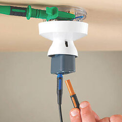
lightmates are a brilliant idea.pity they won't work with megger leads.
I think they work with Meggers if you reverse the leads
 
lightmates are a brilliant idea.pity they won't work with megger leads.
I think they work with Meggers if you reverse the leads
 

Similar threads

OFFICIAL SPONSORS

Electrical Goods - Electrical Tools - Brand Names Electrician Courses Green Electrical Goods PCB Way Electric Underfloor Heating Electrician Courses Heating 2 Go Electrician Workwear Supplier
These Official Forum Sponsors May Provide Discounts to Regular Forum Members - If you would like to sponsor us then CLICK HERE and post a thread with who you are, and we'll send you some stats etc

Advert

Daily, weekly or monthly email

Thread Information

Title
2391-52 practical exam help
Prefix
N/A
Forum
Periodic Inspection Reporting & Certification
Start date
Last reply date
Replies
25

Thread Tags

Advert

Thread statistics

Created
Mick duffy,
Last reply from
whiteelectrical,
Replies
25
Views
23,425

Advert