Discuss Earth leakage from unknown source. in the UK Electrical Forum area at ElectriciansForums.net

Reaction score
0
I'm new to this but stuck with an issue, so I'm looking for some help wherever possible. I have just completed a rewire, which I have a potential difference of 60v between MET and disconnected mains earth. It's an RCBO board with type 2 SPD. I have fully tested the installation and have greater than 200M ohm insulation resistance on every live conductor to earth. There are 15 circuits. I have tried to identify the "faulty circuit" initially by testing for voltage between the MET and the disconnected main earth and disconnecting one RCBO at a time. This reduces the potential difference between the MET and disconnected main earth by approximately 2.5-5v. This continues to reduce with the disconnection of each RCBO until 1.5v (induced reading) is shown on meter. It doesn't make any difference on which circuit i disconnect or doing it in any particular order. Once I reinstate each RCBO it gradually climbs back up to 60v. There are no main eqipotential bonds in place due to alkathene services. Ze reading is 0.26/0.955Ka. PME/TNCS supply.
Had a similar fault a few years back where supply transformer was degrading but have been assured by the 4 DNO employees that attended today that this is a different type of supply so not possible in this case but they were unable to find the cause of the fault. Clearly seems like an internal fault, especially as earth spike that was installed by them temporarily showed no potential difference between PME cutout and earth rod. Im confused on how I have the insulation resistance readings I did showing no earth leakage and potential difference dropping incrementally with each circuit. They suggested poor Chinese insulation on cabling allowing small earth leakage on the internal cabling but I'm not buying that.

One final thing. When the house was built, long before the services being installed, I held the underfloor heating plastic pipes which are reinforcedwith steel mesh and I was sure I had a shock. There was no electrical service there at that point and there is a possibility it was static or something else but I know a low voltage shock and that certainly felt like one. May be a red herring but worth mentioning.
I really appreciate any ideas you could send my way. I like a challenge but sometimes I just can't figure it out.
 
Welcome to the forum!

Measuring the voltage between these points makes no sense and is dangerous if the installation MET is left floating. Earth leakage is not measured as a voltage, and finding 60V does not indicate a fault or lack of one. What were you trying to achieve with this measurement and why are you suspicious of the installation if it passes the normal tests?

When the MET is disconnected from true earth, it is free to take up any potential it likes, just like any other disconnected piece of wire or metal. It will be somewhere between 0 & 230V to earth, because a potential divider is formed by the capacitive reactances and insulation resistances to all other conductors and true earth. As there is likely to be lower reactance to N & true earth than to L, and the input resistance of the meter loads it down too, I would expect the MET to settle on a voltage less than half the supply and 60V sounds perfectly realistic. Except that it's a test that shouldn't be done in the first place.

Sorry that's a bit grumbly as a reply to your first post here, we're not always grumbly!
 
If I understand you correctly, you have the MET disconnected and circuits energised? That is a VERY DANGEROUS thing to do, but under the assumption of most circuits being T&E with similar capacitance L-E and N-E you would expect 115V when measured with a high impedance meter (e.g. digital multi-meter), add some additional paths to E from around the installation and getting 60V is not entirely unexpected.

Please, don't do that sort of a test. The only time the MET ought to be disconnected is when dong a Ze test and at all times during that the installation should be isolated (i.e. main incoming DP switch off).

Also using a multi-meter for voltage testing is generally considered unsafe as there are so many ways it can go wrong. If it is a crap meter without protection against high energy faults (e.g. measuring mains voltage when on amps or ohms range) it can explode in your face, if you test for AC on DC range by mistake you see almost nothing but can proceed to kill yourself by accidental contact to the live system, etc.

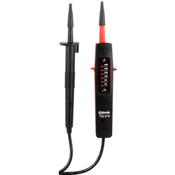
Check your meter is at least 300V CAT-III rated, and please get yourself a voltage tester if you plan on any more work. They are cheap and work even if the battery is flat (some need a battery for continuity bleeping) and as they take a couple of mA to operate the LEDs they are not prone to showing "phantom voltages" due to small capacitive coupling.
 
Welcome! Quite a lot of the places I work I'd give anything for 200M IR on all 15 circuits! Quick - take the money and run!

But anyway, your tests have proved that under fault conditions plenty of amps will flow, there are no cable faults, and presumably you did R1+R2 or R2 for each circuit so there's a sensible resistance CPC for every circuit.
That's enough to say it's safe.

If there was any earth leakage worth writing home about the RCBO would operate. Even if that failed, you've proved that there's a good path back to allow amps to flow and breakers/ supplier fuse to operate.

( I'm sure you see it now, but what your test did was interrupt the CPC path back, so if any class 1 appliance had a fault you'd have been dependant on the RCBO working to stop someone getting a nasty shock from touching the case. )

At least you asked! Stick around, this is a good place to hang out!
 
This sort of thing:

Also remember to test your tester on a known voltage source first, either a dedicated proving unit (the correct way) or if nothing else on a known live socket, etc, before you test anything for real.
 

Reply to Earth leakage from unknown source. in the UK Electrical Forum area at ElectriciansForums.net

Similar Threads

Hi all Suggestions please. I’m working on a 3 phase shop install with a bunch of typical circuits. As each cct is energised the earth leakage...
Replies
6
Views
373
Hi all, There's 2 single fan ovens in the house my mother recently moved into. Posh elecronic AEG units. It's been sat empty for a year, so the...
Replies
19
Views
1K
5 single phases to one huge property. Backup generator which can take about 106 amps split between 2 phases - 1 phase will be wired through...
Replies
2
Views
523
Hello all, I hope you're all keeping well. I have a question regarding insulation resistance testing. Whether doing a single circuit IR test or...
Replies
9
Views
570
  • Question
Hi there, I’m a new member to the forum and felt like I could do with some additional insight into a fault I came across on a call-out at the...
Replies
6
Views
462

OFFICIAL SPONSORS

Electrical Goods - Electrical Tools - Brand Names Electrician Courses Green Electrical Goods PCB Way Electrical Goods - Electrical Tools - Brand Names Pushfit Wire Connectors Electric Underfloor Heating Electrician Courses
These Official Forum Sponsors May Provide Discounts to Regular Forum Members - If you would like to sponsor us then CLICK HERE and post a thread with who you are, and we'll send you some stats etc

Electrical Forum

Welcome to the Electrical Forum at ElectriciansForums.net. The friendliest electrical forum online. General electrical questions and answers can be found in the electrical forum.
This website was designed, optimised and is hosted by Untold Media. Operating under the name Untold Media since 2001.
Back
Top
AdBlock Detected

We get it, advertisements are annoying!

Sure, ad-blocking software does a great job at blocking ads, but it also blocks useful features of our website. For the best site experience please disable your AdBlocker.

I've Disabled AdBlock