Soulsurfer

~
Arms
Feb 21, 2013
612
165
118
Channel Islands
Business Name
M.B.S ELECTRICAL
Basically been asked to look into a solution for a customers dwelling / dwellings where they have flats in the same building as they live. At present has old mostly 2 gang switching along ground hallway and up various stairways and between landings and these are junction box wired from two seperate cu's one at entry hall and very last lights from near top floor small cu, the cabling is full of the old di-isoctyl phthalate (Green goo) and as tenants are leaving the switches on all night etc.. and costing them a fortune in electricity bills, they would like some kind of time lag or similar switching arrangement implemented.

Sounds easy enough only the latest kit he supplied for me to try and fit were Time guard ZV810's with PIR built in to them. 2 Gang switch near front door operating porch outside light 1 way and second gang is 2 way to bottom of stairs 2 gang. Only red, yellow, blue 3 core at switches as per JB system. Wired 3 core from existing switch into the ZV and it worked fine with one fitted each end, go to next gang at bottom of stairs linked presumably to 1 of 2 gangs on next stair landing and if a ZV / lag switch fitted there it would not work at all ! So started belling out cores to check cables were going to right places lol, and while checking afterwards I found I have all kinds of weird voltages floating around the 2 way switch terminals while switches are in different positions !

So so far a few different types of time lag switches haven't worked on the shoddy arrangement and I'm not sure any will without rewiring the hall and stairwells all the way up which would be very awkward.
As far as having say stray voltages on jb wired 2 way lighting I have seen that a few times on old houses etc.. is this likely a borrowed neutral issue or other ropey connection problem likely ?

Voltages I have got were not with a true rms tester but a Fluke T5 so might be part of the problem ?
I had for instance 60V between strappers and com to strapper in one position and then 40V strapper to cpc and when switch position operated I'd get 240V between one core and cpc but 2 other cores to cpc reading 24V for both ! Weird as..
 
Yes you do get capacitovely coupled voltages appearing on strappers, this is perfectly normal and happens regardless of how it is wired.

You can easily fit time lag switches to an existing lighting circuit, however it is wired, as long as it works with normal switches fitted.

If you include a precise and accurate drawing of exactly what is in place then we may be able to help you more specifically. Failing that your only option is to get a competent electrician to do the job.
 
if you do not know what your doing, then your going to get into trouble with two way switchs,
They are wired differently to normal switchs,
do you understand the difference ?
 
You would have to be sure of the wiring arrangement for the two way switching before you wired the sensor in place of the switch.
If the wiring was 3 wire not 2 wire then the connections will need to be different.
Some of the sensors that do not use a neutral have some problems with receiving power through fluorescent and LED lighting.
Ignore the odd voltages and concentrate on the 230V measurements, though if the lights are working correctly with plate switches then you only need to identify line and switched line and carry on from there.
As far as the ones he has now to use as replacement they are 2 wire as no need for Neutrals, you can use two of these in parallel or one and a retractive which I also tried but the 2 way wiring itself doesn't seem right that's all it is not that I don't know how to wire a 2 way circuit or any of that rubbish like two over keen to be passive aggressive commenters above have posted ! unfortunately you always seem to find these type of people who would rather insult then help a little. :-(

I get that sometimes you have odd voltages with capacitive coupling but it's just the fact that no arrangements that he has tried in the past with his previous electrician or now with my trying to fit his new chosen switches will operate correctly and the tech lad at timeguard had no clue either as to why ? as he agreed that when I told him what is there that it should work.
 
if you do not know what your doing, then your going to get into trouble with two way switchs,
They are wired differently to normal switchs,
do you understand the difference ?
Please don't be silly, I know very well the difference ! I've been wiring them a very long time now ! This is just a fact that the place involved here is very odd and has had a lot of bodged work in the past highlighted when altering and replacing the basement and ground floor to create the client a private home at the lower two levels. The rest was untouched and there are weird wiring methods all through it etc..
 
If the lights work normally then there must be a means, however it is connected, that allows the line (or possibly the neutral though very unlikely, but it might be worth checking polarity) to reach the switch and a switch line to leave the switch.
Therefore once you have these then you can connect the sensor, ignoring the other switch temporarily (though you may need to bypass it if you have no permanent line), to see if the sensor works. once it is working then you can move on to connecting the other end via the appropriate links, but it will all start with getting the line and switched line at one switch.
Yes I get what you're saying of course it just seems that some kit requires only the line & S/l connected and then parallel wired to another switch the same or sometimes via a slave trigger switch or retractive as a slave but if so i'm thinking what about the extra strapper ? as this would not be needed at all as all the switches i have seen all only connect as a 1 way type connection. Thanks
 
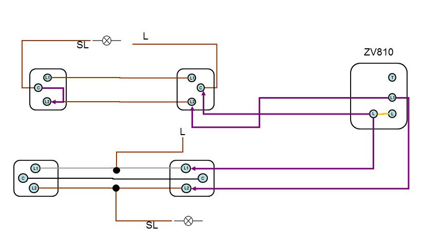
The ZV810 has an L, L1 and trigger.
L and L1 are connected together once operated, this is either via the sensor or by applying or removing voltage at the trigger.

Initially identify the switches line and switched line wiring and temporarily connect as in the below diagram to test the sensor works; once you have this you know the correct wiring is identified then you can rearrange the wiring to suit the application.
If you want sensors at both ends so that either one will connect to a line when either one is operated then the permanent line goes to opposite terminals at each sensor as does the switched line.
Any core not required can just be terminated in the back box.

ZV810 test sensor works.jpg
 
Is it feasible to joint out the switches so a permanent live is at all lights then just fit some Led fittings with microwave detection in the light ?
 
  • Like
Reactions: Leesparkykent
Is it feasible to joint out the switches so a permanent live is at all lights then just fit some Led fittings with microwave detection in the light ?
Yes most likely able to do that although would then need to blank off all switch boxes in walls. Was back there today sorting a fault on two hot water cylinders ! But after spending time testing the switching arrangements there is something very odd somewhere as some legs are working perfectly with time lags in place and the first stairs leg is not working at all with any time lag ! I'm going to try and mess about with the switches tonight on a small test rig I have at home.
 

Similar threads

OFFICIAL SPONSORS

Electrical Goods - Electrical Tools - Brand Names Electrician Courses Green Electrical Goods PCB Way Electric Underfloor Heating Electrician Courses Heating 2 Go Electrician Workwear Supplier
These Official Forum Sponsors May Provide Discounts to Regular Forum Members - If you would like to sponsor us then CLICK HERE and post a thread with who you are, and we'll send you some stats etc

Advert

Daily, weekly or monthly email

Thread starter

Soulsurfer

Arms
~
Joined
Location
Channel Islands
Business Name
M.B.S ELECTRICAL

Thread Information

Title
Old building lighting issues!
Prefix
N/A
Forum
Lighting Forum
Start date
Last reply date
Replies
10

Advert

Thread statistics

Created
Soulsurfer,
Last reply from
Soulsurfer,
Replies
10
Views
2,382

Advert