H
hicksde
Apologies for what I am sure will turn out to be a noob error/misunderstanding, but I've done all the tests I can think of and cant make sense of what I'm seeing...
Basically I have a 3 lighting zones (13x GU10 downlights in total), each using one of the standard 2way dimmers that make up a 3 gang switch. One of the zones also has a regular 2way non-dimming slave.
I am planning to replace the 3 way with a Varilight Eclique dimmer, and the slave with the corresponding Varilight slave, but before I got started I did some tests to make sure the current wiring was clear to me. Which is where it got strange!...
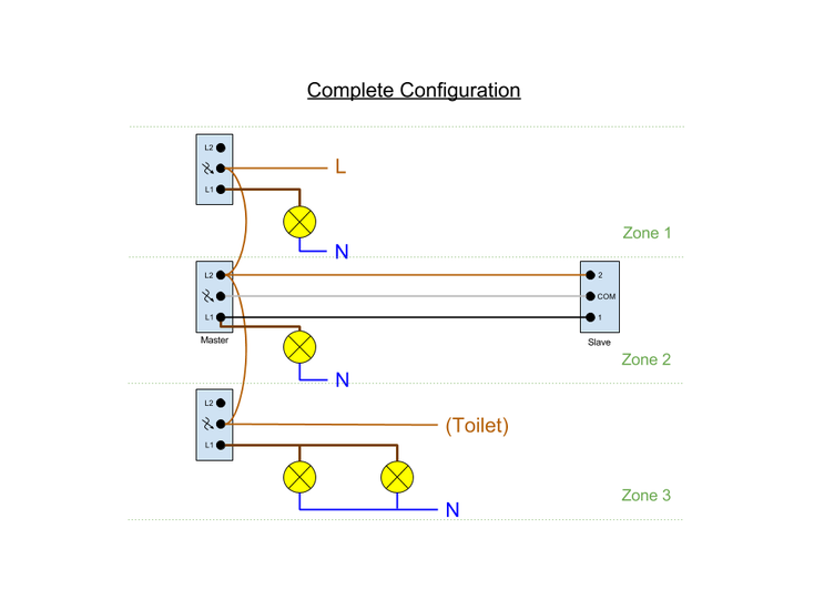
Having spent way too long with my meter I am reasonably confident that the following diagram accurately represents how things currently stand, with all lights and switches working correctly :

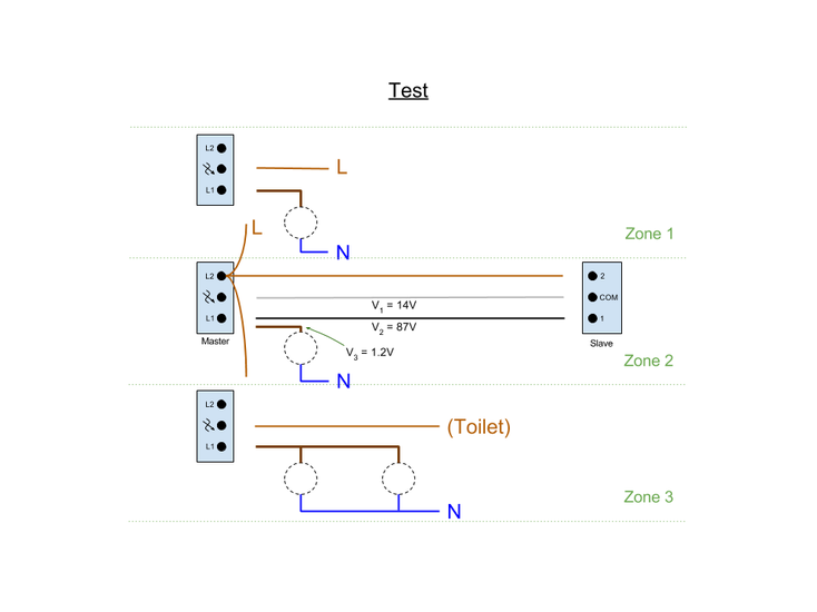
(ignore the Toilet feed and the extra light in zone 3 (which isnt actually connected yet), I just wanted a complete diagram for my own reference). Hopefully there's nothing too badly wrong with that picture(?), but when I then disconnect EVERYTHING except the live feed to zone 2 master (all 13 bulbs out, all terminals disconnected as shown below) and measure the voltage on the remaining 3 wires that normally connect to that master I get numbers that I just cant get my head around :

The only conclusion I can come to is that those wires have connections to something I have no visibility of, but why the strange numbers? (ie. I'd have thought they'd be pinned up to the full 240 or down to 0 in that case). I did continuity tests from both ends of the grey and black wires to all other points on that diagram and found nothing.
Any suggestions will be very gratefully received please? I dont feel confident that swapping in the Varilights is safe until I understand whats going on here, so I'm kinda stuck!...
Thanks in advance
Basically I have a 3 lighting zones (13x GU10 downlights in total), each using one of the standard 2way dimmers that make up a 3 gang switch. One of the zones also has a regular 2way non-dimming slave.
I am planning to replace the 3 way with a Varilight Eclique dimmer, and the slave with the corresponding Varilight slave, but before I got started I did some tests to make sure the current wiring was clear to me. Which is where it got strange!...
Having spent way too long with my meter I am reasonably confident that the following diagram accurately represents how things currently stand, with all lights and switches working correctly :

(ignore the Toilet feed and the extra light in zone 3 (which isnt actually connected yet), I just wanted a complete diagram for my own reference). Hopefully there's nothing too badly wrong with that picture(?), but when I then disconnect EVERYTHING except the live feed to zone 2 master (all 13 bulbs out, all terminals disconnected as shown below) and measure the voltage on the remaining 3 wires that normally connect to that master I get numbers that I just cant get my head around :

The only conclusion I can come to is that those wires have connections to something I have no visibility of, but why the strange numbers? (ie. I'd have thought they'd be pinned up to the full 240 or down to 0 in that case). I did continuity tests from both ends of the grey and black wires to all other points on that diagram and found nothing.
Any suggestions will be very gratefully received please? I dont feel confident that swapping in the Varilights is safe until I understand whats going on here, so I'm kinda stuck!...
Thanks in advance


