Discuss Hot Tub GFCI troubleshooting in the UK Electrical Forum area at ElectriciansForums.net

This is so important please could you post a better picture so those 'in the know' can confirm the wiring is actually correct for you.

I agree completely. I took some new photos, moved the wires to get a better view, and also annotated them. I left the same pics un-annotated so you can see. Please let me know what you think!
[automerge]1587526321[/automerge]
I ran some additional tests. I reconnected the light and I ran 2 tests. I'm interested to see what you think about my conclusions.

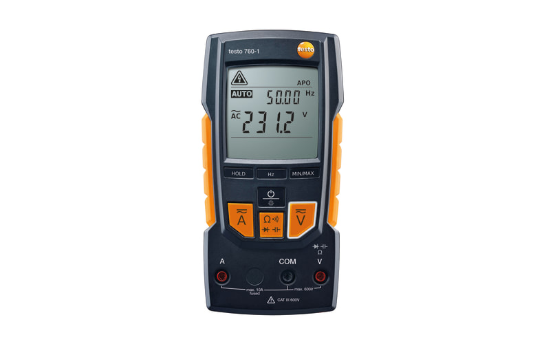
The voltage I measured with one lead in the water and the other into the earth directly. A DC measurement showed 0 while an AC measurement showed roughly 20V. So to me this means it's VAC not DC. I also included a picture of the transformer inside the hot tub control board and also a copy of the circuit diagram for fun too.

I wanted to know how much current was leaking so I had one lead in the water and the other in the earth. I tried the 10A amp option first it read nothing, then I went to the 200mA option input and with the DMM on the 200u it showed 11.1.

Does this mean it's an 11uA shock at 20V? I am concerned this isn't an accurate reading because the DMM is in parallel with the light circuit which is still connected and I'm not sure how I could measure this otherwise. If I measured the light circuit directly it wouldn't account for the significant loss in conductivity due to the water.

If you have suggestions for how I can accurately access the voltage and amperage, or if my conclusions aren't accurate.
 

Attachments

  • incoming_breaker_annotated.jpg
    117.4 KB · Views: 6
  • incoming_breaker.jpg
    88.7 KB · Views: 6
  • hot_tub_annotated.jpg
    126.5 KB · Views: 4
  • incoming_breaker_2_annotated.jpg
    140.6 KB · Views: 4
  • incoming_breaker_2.jpg
    112.6 KB · Views: 6
  • transformer.jpg
    82.9 KB · Views: 6
  • voltage_test.jpg
    115.7 KB · Views: 7
  • current_test.jpg
    135 KB · Views: 8
  • circuit_diagram.jpg
    126.6 KB · Views: 12
Last edited:
I wanted to know how much current was leaking so I had one lead in the water and the other in the earth. I tried the 10A amp option first it read nothing, then I went to the 200mA option input and with the DMM on the 200u it showed 11.1.
Your meter is measuring DC current, not the AC!

AC is typically used for low voltage lights, originally halogen bulbs for which DC is not needed.

This also provides a real-world example of why for safe isolation you should use a voltage tester and not a multimeter. A multimeter on the wrong setting can be lethal, either exploding (if on amps or ohms and not able to safely interrupt the fault current) or giving you a false sense of security (as here, if measuring DC volts on a AC supply it would read next to nothing).
 
If you are thinking of a new multimeter this one (and the 760-2 bigger brother) are liked by some on this forum:
Unlike many of the cheaper meters, it has the CAT-IV rating to 300V so is acceptable to test incoming domestic power lines as covered here:
There are many other meters available, but this seems a good price/performance point. Same for voltage testers, avoid the non-contact type and the best are usually the simplest but should always have at least the CAT-IV rating to 300V or more for domestic use. Same brand, but plenty others of similar sort:
[automerge]1587555829[/automerge]
I see that HomeDepot has the Klein Tools ET45 voltage tester for $9 and it is CAT-III rated to 350V so fine for stuff from your breaker board, etc.
[automerge]1587556623[/automerge]
Remember with any test equipment if you are trying to prove something is dead and safe to work on, you have to prove that your tester is working first!

You can get battery powered proving units for this task so you can check before and after you verify the power is off (circuit dead) but the basic alternative is you use the voltage tester on a known power source first (and after, if possible) so you know the tester is working.
 
Last edited:
https://spacare.com/productimages/pdfmanuals/Balboa/Testing_A_Balboa_Transformer.pdf

Could you identify which 12V transformer is fitted to your hot tub? I think it is the first one written in red in the link above.

The transformer is a 30274-2. It has 30274 on the side and as described in the the Balboa link it has 3 wires (one black hot primary, two secondary yellows) in the connector. The 4th wire (white primary) is connected to the breaker. That would make it the 30274-2.

The primary side resistance test (black wire in connector and the white neutral) showed 45 ohms. That is within the recommended range of 40-50 ohms. The secondary side resistance test (between the two yellow wires) showed 0.9 ohms which is within the recommended range of 0.5 - 1 ohm.

I measured resistance between the black (primary) and one of the yellow (secondary) and it showed no ohm value. I measured resistance between the black (primary) and ground and it also read 45 ohms which I can't tell if its strange or not. I measured between a yellow (secondary) and ground and it showed infinite resistance.
 
Your meter is measuring DC current, not the AC!

AC is typically used for low voltage lights, originally halogen bulbs for which DC is not needed.

Thank you for pointing this out! I have another tester which is able to measure AC correctly. So here's those same tests redone with that one (along with a new amperage pic). The water is putting out 20VAC and 3.21A.

So in summary how dangerous are these numbers?

Conceptually I understand from Lucian Nunes that the GFCI wouldn't trip because the light is on the other side of the transformer. Still though, this seems like an unbelievable safe design from the manufacturer. What do you think?
 

Attachments

  • IMG_20200422_190522.jpg
    113.7 KB · Views: 6
I really doubt you are seeing 3.21A of leakage! I don't think you are using the meter correctly as it appears to be a clamp meter where for measuring current you put the current-carrying conductor in to the centre of the jaws.

A sustained current of 0.03A (30mA) is considered the upper limit where you are probably (95%) going to survive a shock. See this graph:
 
The water is putting out 20VAC and 3.21A. So in summary how dangerous are these numbers?

Agree that 3A doesn't make sense, the resistivity of the water is much too high to allow that. 3mA possibly but does that meter even take current readings from the probes or just through the clamp?

Voltage on its own means nothing when there is no complete circuit. Take a piece of electronic equipment such as a Blu-Ray player or TV that has a 2-prong plug, stand it on an insulating surface and measure the AC voltage between the shield on one of its connectors and ground. You might get anywhere between zero and 120V, it doesn't matter, it's a fraction of a milliamp of leakage through a high impedance and the actual number you see only tells you how that impedance compares to the input impedance of your meter. Different meters will tell different things. Whatever, you don't get shocked.

So at the moment we can't infer anything from the numbers, because the voltage doesn't tell us anything and the current is incorrect.

You measured some aspects of the transformer. The primary and secondary resistance readings are normal and simply tell you the transformer probably works. The one of interest is between primary and secondary and you didn't get a reading which means it's off the scale at 20MΩ or whatever. But that is not an adequate test of insulation as the test voltage is not representative of the electrical stress in normal use. To prove the integrity of the insulation, one needs a high-voltage insulation tester that measures the resistance while subjecting the insulation to a high voltage such as 250 or 500V.

Personally, I would test the insulation resistance and differential leakage of the entire hot tub installation. That would be routine in the UK although it seems less common in the US. If it passes those tests with a good margin, we can debate the merits of underwater transformer-fed lighting and GFCIs for ELV circuits safe in the knowledge that you are unlikely to suffer a life-changing shock from the AC line through a fault as yet undiscovered.
 
You both are right. I was using the meter incorrectly. After reading it's instructions the clamp style meter only measures voltage with the probes. I used some 12 gauge copper wire, connected the electrified water to the earth and used the amp clamp, but it measured 0. I read the instructions and realized this gauge reads a minimum of 0.01A in its AC setting on the 40A range. So I don't have the equipment to measure this more accurately.

I appreciate the suggestion for the Testo. I think I am going to get one and measure it. The tub is out of commission through the summer anyway so it can wait for delivery. This is a learning project for me so that's my interest.

I will have a certified electrician verify the wiring before anyone gets in it no matter what.

Personally, I would test the insulation resistance and differential leakage of the entire hot tub installation.

What tools would you use to perform the insulation resistance and differential leakage tests? What can I read to learn more how to conduct such tests? How can I learn more?
 
I appreciate the suggestion for the Testo. I think I am going to get one and measure it. The tub is out of commission through the summer anyway so it can wait for delivery. This is a learning project for me so that's my interest.

I will have a certified electrician verify the wiring before anyone gets in it no matter what.
That is good to hear!

What tools would you use to perform the insulation resistance and differential leakage tests? What can I read to learn more how to conduct such tests? How can I learn more?
The leakage current measurement for distribution circuits is usually done with a clamp ammeter as well, but one that can go down to less than 1mA resolution since you would normally be expecting values in that range.

To measure the residual current (basically what trips a GFCI) you would clamp the phase (hot) wire(s) and the neutral all together but not the earth. Normally (say 2-wire system) what goes out on one wire comes back on the other so they should always sum to zero, and the net magnetic field would also be zero. If something is leaking from live to earth then there will be that difference when looking at L+N (as N would be missing the leakage return) and the meter would read that.

There was a discussion on here about what sort of meter to get for this type of work here:
Probably similar ones are available in the USA. While not greatly expensive they are often a bit out of most DIYer's price range.

For testing an appliance you can get dedicated test meters for that sort of thing. In the UK they are referred to as "PAT testers" (PAT standing for Portable Appliance Testing) and they generally do several tests but the key ones are earth continuity, insulation resistance (DC test) and earth leakage current (AC test). More can be read here:
The cheapest models just give a pass/fail result and are intended for non-skilled use, for example, a company who sends someone who is not an electrician on a short course so they can check stuff internally as it is cheaper and/or more flexible than contracting work to a 3rd party. The more advanced (and expensive) models give readings and allow more tests for handling unusual cases and typically are used by folk who do PAT testing commercially.

Quite a lot of what an advanced PAT tester does is duplicated in a Multi Function Tester (MFT) that typically an electrician would have instead to allow earth conductor resistance, insulation testing and RCD trip-time measurements, etc, but both have areas of testing that the other one lacks.
 
Last edited:
Well I got the testo and I tested the shorting underwater light what I believe is correctly this time, pic for amp measurement attached. It reads a stable 0.76 mA and 20V. Notice it also shows a nearly perfect 60Hz signal. Image upload seems to not be working on the forum so here's my pic link: New photo by Brian Bouterse - https://photos.app.goo.gl/hXwTB2GniHrXwvDf9

So that's the kind of power we're working with. It's less than 5mA which explains why the GFCI doesn't trip. Do you agree?

That looks like a more realistic figure.
 
What is the meter actually measuring there? Pool water to true ground? Clearly that current wouldn't trip.a GFCI and isn't likely to be harmful, but I'm still not sure what it represents. Aggregate leakage from the whole electrical system? Leakage across the lighting transformer? Difference between supply ground and true ground? We're only seeing the symptom, not the cause. Insulation tests and differential leakage tests will locate its source...
 
Certainly that reading looks more realistic, though as Lucian has said, it is not clear exactly where you are measuring this (i.e. what is each probe connected to)?
 
I should have given info about how the test was conducted in addition to the data observed. Thank you for teaching me this lesson also.

The test performed was with 1 probe in the water itself, and the other in the dirt/earth next to the tub. The dirt is very dense, so I believe it provides direct, low impedence conductivity to the earth.
 
It depends what you are comparing it to. There could still be many kilohms or tens of kilohms between your probe and true earth, insignificant when taking a voltage reading, significant when measuring current and barely conductive at all compared to the main ground connection.

But the law of diminshing returns sets in about now. You have some measurements that imply there is some leakage that might be worth investigating, albeit that the leakage only occurs via the present path when the insulation of the underwater lights is compromised. If you want to trace its source, then tests of a more specific and targeted nature are required. I can come up with about half a dozen completely different explanations for your 20V and 0.76mA, but with a dozen other tests I could prove or disprove each theory, in a logical sequence. We don't have much info (not being there with you) and you don't have much test equipment, so I am not sure how far we can help with that. It might be the time to get a service agent or electrician skilled at fault-finding to give it a proper series of tests.
 
The test performed was with 1 probe in the water itself, and the other in the dirt/earth next to the tub. The dirt is very dense, so I believe it provides direct, low impedance conductivity to the earth.
You would be surprised by how hard it is to get a genuinely low earth rod impedance!

Even so, the test you did implied an impedance of around 26k but a portion of that could be the test probe in to the ground. That would make little difference to the 20V you see, but might impact on the current you observe. Same goes for the size of the conductive object in the water, if you have a foot or two of bare wire in the water it would be better connected to the source.

I would be reluctant to suggest you drive in an earth rod for the sake of it as you might just hit a buried cable/pipe, but you could try using a long wire to an internal (power supply) earth, or something like a metal water pipe entering the building.

But as already said, you have shown readings that are more in keeping with the failed low voltage light than a leak from the AC power itself.
 
I had an electrician company that deals with hot tubs specifically come out, and they confirmed the tub, GFCI, and electrical disconnect are all wired correctly. Also the wires going through the hole now have a grommet.

Unfortunately this hot tub electrician could not perform the earth leakage current test, perform RCD trip time measurements, or perform the insulation resistance test. It's frustrating to understand these tests, yet when I asked about them they say things like "what is that" or "that sounds complicated". :(

Thanks for all the help from this forum!
 

Reply to Hot Tub GFCI troubleshooting in the UK Electrical Forum area at ElectriciansForums.net

Similar Threads

Replaced our old 240v hot tub with a new one, which also uses 240v for motors, heater, etc, and 120v for low amp LEDs and touch screen control...
Replies
4
Views
1K
Extremely low voltage on 120v line Hi, I’m not an electrician but my home has 20 amp breaker that has only one outdoor outlet on it with a GFCI...
Replies
2
Views
554
Hi, My hot tub keeps tripping after 12 years of use. I'm thinking it's the GFCI gone bad. Unfortunately it's a CH 2 pole 50 amp (GFTCB250) and...
Replies
1
Views
885
Hello, I had an electrician install a 100Amp subpanel which feeds a mini split. I addition I added a Homeline 50A GFCI breaker to power a shed. I...
Replies
9
Views
2K
Hello and thank you for your time. In the picture, the 6/3 gauge NMD wire is running though the basement ceiling and out of the house into the...
Replies
6
Views
1K

OFFICIAL SPONSORS

Electrical Goods - Electrical Tools - Brand Names Electrician Courses Green Electrical Goods PCB Way Electrical Goods - Electrical Tools - Brand Names Pushfit Wire Connectors Electric Underfloor Heating Electrician Courses
These Official Forum Sponsors May Provide Discounts to Regular Forum Members - If you would like to sponsor us then CLICK HERE and post a thread with who you are, and we'll send you some stats etc

Electrical Forum

Welcome to the Electrical Forum at ElectriciansForums.net. The friendliest electrical forum online. General electrical questions and answers can be found in the electrical forum.
This website was designed, optimised and is hosted by Untold Media. Operating under the name Untold Media since 2001.
Back
Top
AdBlock Detected

We get it, advertisements are annoying!

Sure, ad-blocking software does a great job at blocking ads, but it also blocks useful features of our website. For the best site experience please disable your AdBlocker.

I've Disabled AdBlock