W

Welshgixxer

Hi all

From the outset I'm not in an electrician. I am posting here because I'm thinking the subject matter is quite specific and will prob require some historic knowledge/ experience - I'm hoping someone will allow me to benefit from their knowledge.

I am converting a Bradbury 4 post lift (a variation of a liftmaster 735, which I think is a mk1/2) from 3 to single phase - single direction motor.

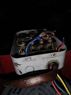
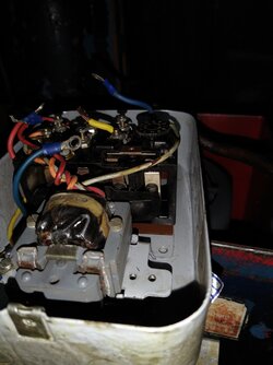
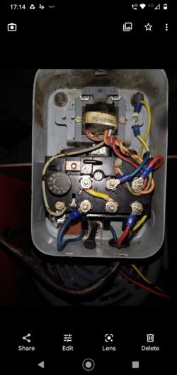
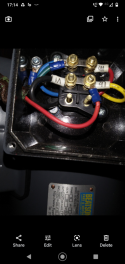
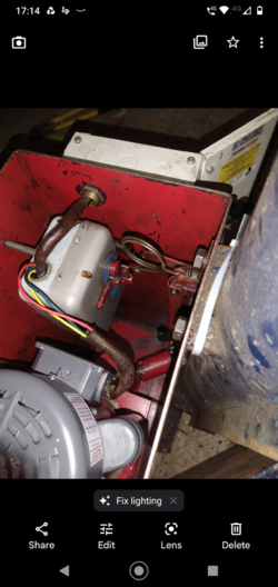
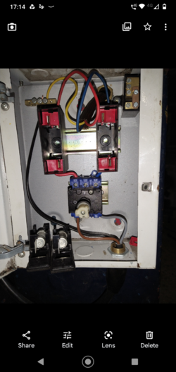
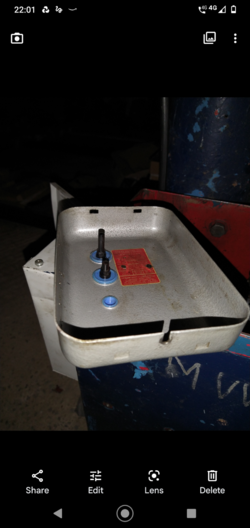
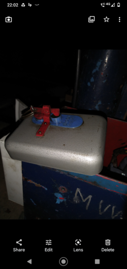
The issue I have is with the Dol starter. I want to replace the 415v original with a 230v dol starter with overload. The original dols is housed within the oil reservoir and the (dols') on/off buttons are 'pushed' via a mechanical rod & linkage setup connected to the up/down lever on the main post.

I'm thinking I need to either retain the original dol metal enclosure, replacing it's innards OR replace the entire box.

Simplest would appear to be to retain the original enclosure - thus retaining the mechanical on/off linkage - problem would be the successful marriage of the enclosure on/off buttons with the new internals.

Anyone thoughts/ experience/ solutions of/ for this scenario more than gratefully received.

photos attached (hopefully)-
 

Attachments

  • Screenshot_20220212-101242.png
    Screenshot_20220212-101242.png
    2.1 MB · Views: 295
  • Screenshot_20220212-131604.png
    Screenshot_20220212-131604.png
    1.7 MB · Views: 143
  • Screenshot_20220212-131619.png
    Screenshot_20220212-131619.png
    1.5 MB · Views: 168
  • Like
Reactions: timhoward
I have a few thoughts, based on a series of assumptions that might quickly collapse like a house of cards! But to get the ball rolling....

I'm first assuming that in original 3 phase mode the Down operation basically opens the hold-on contact to ensure the motor is stopped, and also simultaneously operates the hydraulic recirculation valve mechanically.
So first principles are that you trying to energise the pump for UP, and for DOWN you are trying to mechanically recirculate the hydraulics while ensuring the pump isn't running.

I can't really see from the photo's exactly how it works, but my further assumption is that the UP operation originally manually closed the contactor while energising the coil to hold the contactor there?

If so my thinking would be to leave the original starter in place, using it as a simple two wire "make" switch that closes contacts when the control handle is moved to "UP" and in all other states the contacts would be open.
These could be used to energise a new contactor for the new 230v pump.
You would then be holding the lever in the UP position to ascend, let go and the pump would stop.
Down would be purely mechanical using the existing setup.

Apologies if I've misunderstood how it works. There are finer minds than mine on this forum that in due course I'm sure will have more ideas. ( @pc1966 @Lucien Nunes ).
 
  • Like
Reactions: Jim_e_Jib
I have a few thoughts, based on a series of assumptions that might quickly collapse like a house of cards! But to get the ball rolling....

I'm first assuming that in original 3 phase mode the Down operation basically opens the hold-on contact to ensure the motor is stopped, and also simultaneously operates the hydraulic recirculation valve mechanically.
So first principles are that you trying to energise the pump for UP, and for DOWN you are trying to mechanically recirculate the hydraulics while ensuring the pump isn't running.

I can't really see from the photo's exactly how it works, but my further assumption is that the UP operation originally manually closed the contactor while energising the coil to hold the contactor there?

If so my thinking would be to leave the original starter in place, using it as a simple two wire "make" switch that closes contacts when the control handle is moved to "UP" and in all other states the contacts would be open.
These could be used to energise a new contactor for the new 230v pump.
You would then be holding the lever in the UP position to ascend, let go and the pump would stop.
Down would be purely mechanical using the existing setup.

Apologies if I've misunderstood how it works. There are finer minds than mine on this forum that in due course I'm sure will have more ideas. ( @pc1966 @Lucien Nunes ).
Thanks Tim

You are way ahead of my basic understanding of the existing set up. I think your assumptions are correct. However the existing circuitry is not working.

I purchased the lift 10 years ago - erected it, parked a car on it and then life got in the way. A few weeks ago I cleared the debris, bought a single phase motor & wired it up using existing dols and fused rotary isolation switch (mounted externally to the oil reservoir)

On investigation I found the internals of the rotary isolator to be stripped - it could not have functioned - so replaced.

I have wired the now working isolator to the single phase motor via the existing dols. I have no output (from the dols') to the motor so assumed either fried (like the isolator) or not working due to lack of 230v coil.

I appreciate your time and certainly do not wish to waste it - would any additional photos be of help to you?

Si
 
The starter coil appears to have four leads, which suggests it might be dual voltage. Check any attached labels e.g. inside lid for evidence to that effect. Also check whether the overload relay will adjust to the FLC of the single-phase motor. It probably won't but worth ruling that out before you start modding.

Failing that you can probably use the start and stop contacts in the original starter to control the new one. This will require testing the internal configuration to identify the correct terminals. Are you armed with a multimeter?
 
I have wired the now working isolator to the single phase motor via the existing dols. I have no output (from the dols') to the motor so assumed either fried (like the isolator) or not working due to lack of 230v coil.
I'd split this into stages, first check the UP lever manually closes the contactor.
More assumptions.....
You should find that the top row of 3, A B and C are respectively joined to the bottom row of 3 when UP is activated. Check with a multimeter on the continuity setting. So A should show continuity to the one under it, B should show continuity to the one under it etc. You might need to extend wires out of it to test this. (Obviously this is all with power off!)

I suspect the top right hold-on terminal is permanently joined to one of the top 3 internally, most likely the terminal marked C.
Again, check this with a multimeter. As originally configured this would send 400v to the coil once the contactor closed.

Once these principles are confirmed it is possible to wire it for 230v, subject to the coil being dual voltage as Lucien suggested.
 
  • Like
Reactions: Jim_e_Jib
I'd split this into stages, first check the UP lever manually closes the contactor.
More assumptions.....
You should find that the top row of 3, A B and C are respectively joined to the bottom row of 3 when UP is activated. Check with a multimeter on the continuity setting. So A should show continuity to the one under it, B should show continuity to the one under it etc. You might need to extend wires out of it to test this. (Obviously this is all with power off!)

I suspect the top right hold-on terminal is permanently joined to one of the top 3 internally, most likely the terminal marked C.
Again, check this with a multimeter. As originally configured this would send 400v to the coil once the contactor closed.

Once these principles are confirmed it is possible to wire it for 230v, subject to the coil being dual voltage as Lucien suggested.
Tim, Lucien, thank you - I will do as suggested tomorrow & revert.
Si
 
I'd split this into stages, first check the UP lever manually closes the contactor.
More assumptions.....
You should find that the top row of 3, A B and C are respectively joined to the bottom row of 3 when UP is activated. Check with a multimeter on the continuity setting. So A should show continuity to the one under it, B should show continuity to the one under it etc. You might need to extend wires out of it to test this. (Obviously this is all with power off!)

I suspect the top right hold-on terminal is permanently joined to one of the top 3 internally, most likely the terminal marked C.
Again, check this with a multimeter. As originally configured this would send 400v to the coil once the contactor closed.

Once these principles are confirmed it is possible to wire it for 230v, subject to the coil being dual voltage as Lucien suggested.

Tim, Lucien, thank you - I will do as suggested tomorrow & revert.
Si
Tim, Lucien
Tim, Lucien, thank you - I will do as suggested tomorrow & revert.
Si
Tim, Lucien

I'm attaching numerous photos which may/ may not prove useful.

Mechanical external 'up' mechanism appears to close contact (top right, beneath wheel) - but no continuity across A-L1, B-L2, C-L3 when closed

I have manually closed the coil contact and have continuity across A-L1, B-L2,C-L3.

No continuity between top right terminal (1) and any of A,B or C.

Does this help?
 

Attachments

  • IMG_20220213_174312832.jpg
    IMG_20220213_174312832.jpg
    299.7 KB · Views: 89
  • IMG_20220213_174301619.jpg
    IMG_20220213_174301619.jpg
    342.9 KB · Views: 89
  • Screenshot_20220213-171426.png
    Screenshot_20220213-171426.png
    1.6 MB · Views: 101
  • Screenshot_20220213-171420.png
    Screenshot_20220213-171420.png
    1.6 MB · Views: 136
  • Screenshot_20220213-171408.png
    Screenshot_20220213-171408.png
    1.8 MB · Views: 85
  • Screenshot_20220213-171403.png
    Screenshot_20220213-171403.png
    1.7 MB · Views: 95
Another 4 post Bradbury ramp owner here!
Mine was also 3 phase, now converted to single phase, but I didn't change the motor. It was dual voltage, so reconfigured to the lower voltage, with a capacitor to simulate the missing phases, plus another capacitor and current operated switch to provide starting torque. Mine appears to be a newer model than yours, because the original contactor was a more modern type, which I merely changed for a similar one with a 240 volt coil. Been in use and running fine now for about fourteen years.
Regarding your pics in your last post, if the last pic is the single phase converted final version, the incoming neutral should be connected directly to the isolator, bypassing the fuse. The fuse in the live wire should be retained.
 
  • Like
Reactions: timhoward
Another 4 post Bradbury ramp owner here!
Mine was also 3 phase, now converted to single phase, but I didn't change the motor. It was dual voltage, so reconfigured to the lower voltage, with a capacitor to simulate the missing phases, plus another capacitor and current operated switch to provide starting torque. Mine appears to be a newer model than yours, because the original contactor was a more modern type, which I merely changed for a similar one with a 240 volt coil. Been in use and running fine now for about fourteen years.
Regarding your pics in your last post, if the last pic is the single phase converted final version, the incoming neutral should be connected directly to the isolator, bypassing the fuse. The fuse in the live wire should be retained.
Cheers Bri, thanks - I've been in and out of this for months, sometimes minutes at a time, I can't even explain why I did that when I did it and even more confusing, when I took the photo why I didn't see it.
Si
 
  • Like
Reactions: timhoward
The operating controls on mine are two push buttons and a lever. The ramp, when in use doesn't rely on the hydraulic ram to keep it in position - there is a metal bar alongside the ram housing which has rectangular holes in it about every two inches, you raise the ramp slightly higher than you need, then lower it slightly, and a solenoid operated peg pushes into the hole in the bar that is along side it, taking the entire weight of the ramp bed and whatever is on it.
The LH push button on the control panel starts the motor/pump, retracts the peg, and raises the ramp. You then release the button, pull the lever downwards, and the ramp lowers slightly onto the peg.
To lower the ramp, you push the fist button momentarily to raise the ramp slightly and take the load off of the peg. Next, you push the RH button, which powers the solenoid that retracts the peg. This button is held in, and the lever pulled down, which opens the oil return valve, allowing the ramp to descend. To stop the ramp part way down, you release the RH button, peg goes in, then you release the lever, when the peg reaches the bottom of its 2" hole.
Does yours work the same way?
Bri

I remember reading how it works (year, maybe years ago) and will have notes somewhere - from memory, simpler than yours - lever up for up, mechanical lock to hold, lever down returns fluid to tank, lowering lift.
Trying to take it one step at a time - getting it to move 1st.
It came in parts - trying not to be too optimistic seeing as the rotary switch internals were literally in bits.
 
  • Like
Reactions: timhoward
When I bought mine, it had been under three feet of floodwater a couple of weeks earlier!
 
Last edited:
  • Like
Reactions: timhoward
Mechanical external 'up' mechanism appears to close contact (top right, beneath wheel) - but no continuity across A-L1, B-L2, C-L3 when closed

I have manually closed the coil contact and have continuity across A-L1, B-L2,C-L3.
I haven't been able to understand from photos how the lever moves the contact, but is there any adjustment facility? It sounds as though it is supposed to fully close the contact.
 
I haven't been able to understand from photos how the lever moves the contact, but is there any adjustment facility? It sounds as though it is supposed to fully close the contact.
Sorry Tim, I should have provided an explanation to accompany photos. Moving the [post mounted] lever operates (through mechanical linkage) a mechanical spring loaded 'pivot' attached to the Dol starter front cover - which depresses the button (eg green - if lever up) on the Dol starter enclosure. Both buttons have rods attached to their rear - green is the shorter. The green button rod depresses the spring loaded contact plate below the adjustment wheel and completes circuit. I will take a close look to see if I can adjust rod length - if that's what you mean. - I could also wire it up and carefully depress contact manually with cover off - make sense if knew wiring ok first?
 

Attachments

  • Screenshot_20220213-220143.png
    Screenshot_20220213-220143.png
    1.3 MB · Views: 83
  • Screenshot_20220213-220207.png
    Screenshot_20220213-220207.png
    1.3 MB · Views: 80
Looks like you're going to have the problem of either finding a 230V coil for that contactor, or arranging a modern contactor so that it can be operate by the existing mechanical linkage.
Could possibly be solved by a panel mounted pushbutton, as on mine, and two handed operation.
 
  • Like
Reactions: timhoward
It would be a doddle to start again with a new 230v starter and an auxiliary safety button for the UP operation as Brian said.
The main question in my mind now is how "Down" works....I had imagined the DOWN lever was also operating a mechanical oil return, but now the principle of the lever and the rods has been explained I'm shifting to believing it's an electrically operated return valve?
Maybe annotating the photo of the inside of the DOL would help, showing exactly what UP and DOWN are pressing inside.
I'm thinking that as well as interrupting the coil, DOWN must close two contacts somewhere too.
 
If the OP's ramp uses a solenoid operated latch to lock the ramp in position, like mine, and is single lever operated, then there must be contacts to power that solenoid when the lever is pushed down.
It's unlikely that the oil release valve is electrically operated, because that would make it either fully closed or fully open, and wouldn't allow the descent speed of the ramp to be controlled.
 
  • Like
Reactions: timhoward
When I bought mine, it had been under three feet of floodwater a couple of weeks earlier!
Brian, Lucien, Tim

I'm not very good at leaving things I don't completely understand so before I move on to resolve the practical issue of incorporating a 230v dols would someone please confirm the correctness of my wiring diagram.

I am attaching an image of the Dols and my basic wiring diagram interpretation of it. I have coloured in live & neutral to distinguish them from hardwiring.

2 things (I am aware of) I don't understand:
1, why 2 of the wires exiting the coil join at a terminal?; and
2, assuming I can use 'L3-C as I have to provide current to the off switch (NC) when on switch (no) released, any idea how I would facilitate the 'orangey '(on diagram) connection to C?

Ps. The purple highlighted circle on the wiring diagram indicates the rocker that opens the off switch (NC) operated by the red button.

Of course I could have it all wrong!

Won't let me add images- to follow hopefully

Thanks again.

Si
 

Attachments

  • Screenshot_20220214-221003.png
    Screenshot_20220214-221003.png
    1.4 MB · Views: 77
  • Screenshot_20220214-220520.png
    Screenshot_20220214-220520.png
    1.3 MB · Views: 97
Please ignore yellow cable - forgot to remove it.
Oil release to reservoir is mechanical, allowing oil return to reservoir.
 

Attachments

  • Screenshot_20220214-224931.png
    Screenshot_20220214-224931.png
    1.3 MB · Views: 73
I'm not very good at leaving things I don't completely understand so before I move on to resolve the practical issue of incorporating a 230v dols would someone please confirm the correctness of my wiring diagram.
You have the right idea. If there is definitely no continuity between "1" and "A/B/C" with the contactor manually closed that gets interrupted by the Down button, then as you have identified there is a need for the orange wire on your diagram yet nowhere to connect it....
I find myself wondering if the other terminal with the two other coil wires is somehow involved. More testing needed!
2 things (I am aware of) I don't understand:
1, why 2 of the wires exiting the coil join at a terminal?
The theory that Lucien suggested, which seems likely, is that the coil is either two coils or tapped at various points, enabling the supply voltage to vary. There are two things to do to explore this further...
1 - measure the resistance of the two coil wires that are not joined together, the red and ?grey once. Also measure the resistance of all permutations of the 4 coil wires. Report back on that.
2 - confirm that the terminal that has the two wires joined together has no electrical continuity to any other terminal (with the coil disconnected).
2, assuming I can use 'L3-C as I have to provide current to the off switch (NC) when on switch (no) released, any idea how I would facilitate the 'orangey '(on diagram) connection to C
That is indeed the question, see above.
Keep at it, you are doing well!
 
You have the right idea. If there is definitely no continuity between "1" and "A/B/C" with the contactor manually closed that gets interrupted by the Down button, then as you have identified there is a need for the orange wire on your diagram yet nowhere to connect it....
I find myself wondering if the other terminal with the two other coil wires is somehow involved. More testing needed!

The theory that Lucien suggested, which seems likely, is that the coil is either two coils or tapped at various points, enabling the supply voltage to vary. There are two things to do to explore this further...
1 - measure the resistance of the two coil wires that are not joined together, the red and ?grey once. Also measure the resistance of all permutations of the 4 coil wires. Report back on that.
2 - confirm that the terminal that has the two wires joined together has no electrical continuity to any other terminal (with the coil disconnected).

That is indeed the question, see above.
Keep at it, you are doing well!
Thanks Tim,

More images of contactor and resistance values of coils below

In answer:

• Def no continuity between 1 and A,B or C.

• coil contact terminal (labelled 'A' in resistance value table below and orange dot in image) is plastic and purely a means of connecting coil ends

* I think I have found the missing contact terminal I need for the 'orangey' connection - see image of underside of contactor below (green dot) ** here's the thing - you can see a wire has been/ was intended to be connected to it - problem is the other end of that wire seems to be connected to L3 (see image of top of contactor, blue dot) which would provide a permanent live to the off 'switch'

A) would this configuration work?
B) would a better solution be a connection to C (rather than L3)?

On a practical level - if I rewire contactor as above and provide a 'contactor' live between C and the newfound contact terminal on underside - can I make this dols coil work at 230, considering that max o/l of this dols is 7.2 and the new single phase motor states 8.2?

Sorry to answer your questions with more questions, but sense I am close - although poss not close enough!

Ps really appreciate the positive feedback - my mind doesn't lean to circuitry without a lot of persuasion.

Si
 

Attachments

  • Screenshot_20220215-093745.png
    Screenshot_20220215-093745.png
    1.3 MB · Views: 67
  • Screenshot_20220215-093713~2.png
    Screenshot_20220215-093713~2.png
    1.4 MB · Views: 71
  • Screenshot_20220215-093708~2.png
    Screenshot_20220215-093708~2.png
    1.7 MB · Views: 63
  • Screenshot_20220215-093702~2.png
    Screenshot_20220215-093702~2.png
    1.5 MB · Views: 73
  • Like
Reactions: timhoward
Isn't the 'orangey' wire to connect up the auxiliary NO contacts of the contactor and make it into one that holds on?
May be wrong, but I doubt that is required for a hydraulic ramp.
 
Isn't the 'orangey' wire to connect up the auxiliary NO contacts of the contactor and make it into one that holds on?
May be wrong, but I doubt that is required for a hydraulic ramp.
I agree about the purpose, but my take was that it must have been part of intended original design to hold on, otherwise the "down" operation wouldn't need to open the coil using that little rod.
As you imply it would certainly be possible to proceed without this wire in meantime.
 
The possibility of a ramp moving in any way when the controls are not being operated is extremely dangerous.
It takes about 15 seconds for my ramp to go from down to its highest position, so I can't see what 'hold on' would achieve.
 
  • Agree
Reactions: timhoward
The possibility of a ramp moving in any way when the controls are not being operated is extremely dangerous.
It takes about 15 seconds for my ramp to go from down to its highest position, so I can't see what 'hold on' would achieve.
I take your point - I was also nervous about deviating from an apparent design for similar reasons. But I agree that simpler is safer in this case.

Going back to the 230v coil question -
It looks to me as though the bottom line (A to Grey2) coil resistance of 1.61 ohms is for 230v coil operation. Working out which of the two wires currently joined has the resistance given (1.61 ohms) when measured to Grey2 would be the next step. You should then have a pair of wires that will operate the coil / contact when supplied with 230v. (I trust an RCD protected supply is being used for any testing!)
 
Brian, Lucien, Tim

I'm not very good at leaving things I don't completely understand so before I move on to resolve the practical issue of incorporating a 230v dols would someone please confirm the correctness of my wiring diagram.

I am attaching an image of the Dols and my basic wiring diagram interpretation of it. I have coloured in live & neutral to distinguish them from hardwiring.

2 things (I am aware of) I don't understand:
1, why 2 of the wires exiting the coil join at a terminal?; and
2, assuming I can use 'L3-C as I have to provide current to the off switch (NC) when on switch (no) released, any idea how I would facilitate the 'orangey '(on diagram) connection to C?

Ps. The purple highlighted circle on the wiring diagram indicates the rocker that opens the off switch (NC) operated by the red button.

Of course I could have it all wrong!

Won't let me add images- to follow hopefully

Thanks again.

Si


Brian, Lucien, Tim

Sorry for the delay but tonight is the first night I have made it to the shed since.
I'm sure I'll encounter more probs but I rewired the contactor looping N through 2 contacts and isolated 1 coil - it spun the motor - massive thanks to you all.

Ps Tim, yes Rcd

Si
 
I rewired the contactor looping N through 2 contacts and isolated 1 coil - it spun the motor - massive thanks to you all.
Well done. You’ll get there. And then I’m driving my car down to Cardiff to look under it ….. ;-)
 
The possibility of a ramp moving in any way when the controls are not being operated is extremely dangerous.
It takes about 15 seconds for my ramp to go from down to its highest position, so I can't see what 'hold on' would achieve.
Bri

Hope you don't mind - electrically lift works fine. All posts are plumb and ramp level.
Without extra load ramp reaches chest level fine but then seems to struggle - not smooth - slow and hesitant I.e. rise/pause/rise/pause - not jumpy but as if needing to build pressure before continuing. It lowers without resistance - so I am thinking pump/ ram seals need replacing - make sense.
Tried attaching vid but too large

Si
Photo of (fresh) oil reservoir - looks aerated to me - indicate anything? - all new to me
IMG_20220220_121847590.jpg
 
Sounds like either not enough oil in the reservoir or something wrong with the pick up.
Ram seal wouldn't cause this, until enough oil had leaked out to cause problems
 
Sounds like either not enough oil in the reservoir or something wrong with the pick up.
Ram seal wouldn't cause this, until enough oil had leaked out to cause problems
Cheers Bri, came to same conclusion after posting to you. Gemco advised 15l but having checking Bradbury manual - should be 22. Will let lie for a bit, top up and cross fingers for easy fix - lucky I removed Res cover as I had thought mechanical interference on main post and been grinding column to allow free movement - (evidence of historical roller to post contact)
 
Mine has a oil drain pipe back to the sump, connected into the ram housing, just above the top limit of the seal. Every time you raise the ramp fully up, any oil that has passed the seal is returned to the sump.
Does yours have this feature?
 
Mine has a oil drain pipe back to the sump, connected into the ram housing, just above the top limit of the seal. Every time you raise the ramp fully up, any oil that has passed the seal is returned to the sump.
Does yours have this feature?
Into reservoir from pipe (green arrow) through rectangular cut out (green arrow).
The manual I have is for mk1 - quite basic (few pages) - happy to send you a copy if any use.
 
Mine has a oil drain pipe back to the sump, connected into the ram housing, just above the top limit of the seal. Every time you raise the ramp fully up, any oil that has passed the seal is returned to the sump.
Does yours have this feature?
Mine has a oil drain pipe back to the sump, connected into the ram housing, just above the top limit of the seal. Every time you raise the ramp fully up, any oil that has passed the seal is returned to the sump.
Does yours have this feature?
Enters reservoir through pipe (green arrow) through rectangular cut out (blue arrow).

Bradbury manual (v basic) any use to you?
 

Attachments

  • Screenshot_20220220-163802~2.png
    Screenshot_20220220-163802~2.png
    2.4 MB · Views: 67
It works. Celebratory cuppa
We have just put up a used Bradbury 735 MK1, came with no instructions. Our Lube tank is a big square tank, has the motor inside . Can you tell me how much hydraulic oil to put in? Glad you got yours going. We also had to change motor from 3 phase to single, using capacitors? thanks,
 
We have just put up a used Bradbury 735 MK1, came with no instructions. Our Lube tank is a big square tank, has the motor inside . Can you tell me how much hydraulic oil to put in? Glad you got yours going. We also had to change motor from 3 phase to single, using capacitors? thanks,
Manual states 22l - I found out that 15l insufficient - 20l worked fine (lucky as I bought a 20l tub)👍
 
  • Like
Reactions: RAmadu
If you hear the pump start to cavitate when the ramp is nearly fully up, add a bit more. Nothing critical about it.
 

Similar threads

OFFICIAL SPONSORS

Electrical Goods - Electrical Tools - Brand Names Electrician Courses Green Electrical Goods PCB Way Electric Underfloor Heating Electrician Courses Heating 2 Go Electrician Workwear Supplier
These Official Forum Sponsors May Provide Discounts to Regular Forum Members - If you would like to sponsor us then CLICK HERE and post a thread with who you are, and we'll send you some stats etc

Advert

Daily, weekly or monthly email

Thread Information

Title
4 post Bradbury liftmaster dol starter
Prefix
N/A
Forum
UK Electrical Forum
Start date
Last reply date
Replies
44

Advert

Thread statistics

Created
Welshgixxer,
Last reply from
Fatcatbaz,
Replies
44
Views
9,567

Advert