david74

~
DIY
Jan 10, 2019
36
4
50,083
Leeds
If you're a qualified, trainee, or retired electrician - Which country is it that your work will be / is / was aimed at?
United Kingdom
What type of forum member are you?
DIY or Homeowner (Perhaps seeking pro advice, or an electrician)
I have a light that trips the 5A fuse. It trips it regardless if there is bulb in it. And regardless of which neutral wire switch is on (it has two). And it did trip the fuse once after I disconnected the fitting (to eliminate it). Then I hooked a tester to it and for some reason it has stopped tripping it. Fitting shows full resistance 1 but if I connect live and neutral to the ohmmeter with fuse on (switch off), the Ohms fluctuate. After switching the fuse off, the fluctuations gradually not in frequency but in amplitude go down. It is about 4s cycle.

Update: The light in the bedroom next to it, hooked to the same fuse stays firmly on 1. Then going back to the iffy one, fluctuates again. That is with live wire live and neutral disconnected at switch.

 
Last edited:
The pic is not super clear, but you seem to have the black probe in the central terminal block of the ceiling rose (normally the looped in permanent live), and the black probe in the neutral terminal block. So with the breaker on I would expect 240V across the meter leads. But you have it on the ohms range - rather cruel to the meter - so maybe that's what it's telling you!
If you want to fault find by measuring continuity, turn the power off!
 
  • Like
Reactions: DPG
The pic is not super clear, but you seem to have the black probe in the central terminal block of the ceiling rose (normally the looped in permanent live), and the black probe in the neutral terminal block. So with the breaker on I would expect 240V across the meter leads. But you have it on the ohms range - rather cruel to the meter - so maybe that's what it's telling you!
If you want to fault find by measuring continuity, turn the power off!
The light switch is off. The circuit is open. There are 2V. I measured it first. I would normally do voltage first anyway if was not sure if fuse or switch was off. I did not think that terminals were important when measuring resistance.
 
Mystery continues. With light fitting at the ceiling removed, I know took all wires out of one light switch, brushed them with the sandpaper, removed some insulation that may have been between bolt and the wire, put it all back and on attempt to turn on, it tripped the fuse.


I spent a while figuring out how it was connected before taking it apart. It consists from two sets of connectors arranged like that

14
25
36

2 and 5 are bridged and 2 comes from under the socket and 5 leaves up and goes to feed the bedroom switch.
4 and 6 connect to a 2 red wire cable that goes to the other switch on the end of the corridor.
1 is connected to bathroom light, 3 is vacant.

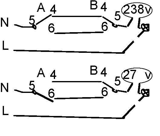
So now confident that the light must be fed through the other switch I disconnected the corresponding 5 on it and measured voltage between 5 and the wire that went in there FIRST and to my astonishment it reads 238V.

The light is not connected. Even the fitting is not. Only the fitting socket with the metal bars with holes. If it has voltage on both ends, I can't make sense out of it.

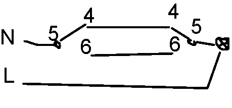
I thought the layout was like this

Untitled-1.png

With bulb removed there should be no voltage between wire and terminal when unplugged.


Why does it have voltage at both ends?

Now if I flip the switch on socket A to 6, it reads 27V on the terminal 5 on socket B and the wire going to light.
 

Attachments

  • Untitled-1.png
    Untitled-1.png
    1.4 KB · Views: 16
Last edited:
Here is a new diagram of how it appears now.

Untitled-1.png
 

Attachments

  • Untitled-1.png
    Untitled-1.png
    3.1 KB · Views: 37
Last edited:
Here is a new diagram of how it appears now.

View attachment 123154
Since you are measuring with a high impedance multimeter, the above is to be expected!
You have mains voltage with the switches closed, ie both 'on'
You have a 'ghost voltage' with them in the 'off' position, and that is because the parallel wires running from switch A to switch B have capacitance between them, and that is coupling a bit of mains to the other wire. The capacitance won't provide much current, so the voltage would disappear if you used a lower impedance measuring instrument.

Normally L and N would be the other way round, ie switches in the live side, and you can't always go by wire colours, but it might have been wired the other way?
 
Last edited:
The light switch is off. The circuit is open.
I was just trying to make the point that, even with light switches 'off', the central terminal block in the ceiling rose would be 'live'. It's normally a feed from the lighting breaker running to all the fittings.
 
Since you are measuring with a high impedance multimeter, the above is to be expected!
You have mains voltage with the switches closed, ie both 'on'
You have a 'ghost voltage' with them in the 'off' position, and that is because the parallel wires running from switch A to switch B have capacitance between them, and that is coupling a bit of mains to the other wire. The capacitance won't provide much current, so the voltage would disappear if you used a lower impedance measuring instrument.

Normally L and N would be the other way round, ie switches in the live side, and you can't always go by wire colours, but it might have been wired the other way?
It could be, I misplaced the screwdriver with the light in it. Since all wire were red, I assumed that they were Neutral because on the fitting the red and the black arrives and it felt that black was the live. I could be wrong.
 
I was just trying to make the point that, even with light switches 'off', the central terminal block in the ceiling rose would be 'live'. It's normally a feed from the lighting breaker running to all the fittings.
Yeah but the problem is that the other light does not exhibit any cycling resistance. I understand that there could be a voltage drop over the wire and the meter would show the difference across the probes. Especially as you say, the impedance is high and the amperage or power is low, hence the noticeable difference.

But it still means there is a leak somewhere. I just wonder if it is between switches or between switch and the light.

If you scroll up to my updated diagram, it now shows 3 different states of the wiring which show three different voltages.
What other setup can I measure?

I tried amperage of that 27V and it read nearly nothing. At least it does not consume much electricity.

The hole between L and the bulb is on purpose because there is no bulb there. I could have deleted the bulb but I want it to show where is source and where is consumption. Sorry, I am making up all this terminology because while I understand the physics, I do not know what they are called.
 
Last edited:
I just calmed down and had a thought and realised that since it does not blow the fuse with switch to bulb wire disconnected, it is the one that needs replacing. Since it is very difficult to access it, I will leave it where it is, disconnect on both ends and rewire it over the wall.
 
It could be, I misplaced the screwdriver with the light in it. Since all wire were red, I assumed that they were Neutral because on the fitting the red and the black arrives and it felt that black was the live. I could be wrong.
The earlier colour code for the UK was Red - live, Black - neutral.
The present colour code as I'm sure you know is Brown - live, Blue - neutral
Lighting circuits often have a black returning from the switch which is actually live, because the red and black in the cable sleeve are both dealing with live.

Readings you pick up on your multimeter can be stray capacitively coupled voltages. If you think you have a leakage fault, eg insulation breakdown somewhere, you need an electrician with the correct test-gear to measure insulation resistance.
 
It worked, I replaced the wire and it now turns on/off both switches. Which means that I have at least located the fault, half job done for a professional electrician to come.
 
I was just trying to make the point that, even with light switches 'off', the central terminal block in the ceiling rose would be 'live'. It's normally a feed from the lighting breaker running to all the fittings.
Central terminal block was not attached to anything. If the red was the live and was switched off at the switch, then the black was not the live, there is even less logic for its resistance to fluctuate.

I actually attached the red to the central block to isolate the fitting. But fitting turned out to be fine. If it was working at least for few seconds, I was going to measure amperage between the central block and the bulb in the right block.

Anyways, that section between switch B and light was iffy, it is now replaced and everything is chicky picky. Obviously if I wanted to sell the house, it would have to be sorted.

I pinched off the bare bits at both ends of the iffy wire and folded them back to minimise any remote chance of it touching anything.
 
Last edited:
  • Like
Reactions: Avo Mk8
Her is the final video. I have a roll of audio cable, it is 0.5-1mm diameter copper which should be fine for the 3W led, but I just used both veins for safe measure.

 
That "bulb" is an accident waiting to happen!
I trust nobody else is around to touch that?
 

Similar threads

OFFICIAL SPONSORS

Electrical Goods - Electrical Tools - Brand Names Electrician Courses Green Electrical Goods PCB Way Electric Underfloor Heating Electrician Courses Heating 2 Go Electrician Workwear Supplier
These Official Forum Sponsors May Provide Discounts to Regular Forum Members - If you would like to sponsor us then CLICK HERE and post a thread with who you are, and we'll send you some stats etc

Advert

Daily, weekly or monthly email

Thread starter

david74

DIY
~
Joined
Location
Leeds
If you're a qualified, trainee, or retired electrician - Which country is it that your work will be / is / was aimed at?
United Kingdom
What type of forum member are you?
DIY or Homeowner (Perhaps seeking pro advice, or an electrician)

Thread Information

Title
Why does it cycle resistance on an open circuit?
Prefix
N/A
Forum
UK Electrical Forum
Start date
Last reply date
Replies
14

Advert

Thread statistics

Created
david74,
Last reply from
Avo Mk8,
Replies
14
Views
870

Advert