Discuss 240V SP Ind Fan Motor wiring help in the Commercial Electrical Advice area at ElectriciansForums.net

plugsandsparks

-
Esteemed
Arms
Reaction score
2,026
Hi guys, struggling with a problem wondered if anyone can help.

Had 2 A/C units failed on me, spare parts not available til end of August... :-(

The faults were caused by the fan units which vapourised tracks on the PCB, great design , not.

I can repair the PCBs but the fans are dual fans that come on at the same time so i am hoping that only one fan has failed and that i can at least get one fan assembly working out of the 2 assemblies i have. I .e. i have 4 fans but need 2 to get going again, so i am trying to test the 4 fans and get 2 good ones

This is what i have done so far.
1. Caps are 5uF just one per fan, all tested OK
2. IR all good
3. Continuity giving different readings across fans but quite frankly cannot work out from that which ones are good or bad.

I believe these fans are dual speed. i.e. high and low.

There are 6 wires coming out of the motor:
2 go to the cap as its external - no problem.
1 is Neutral, again no problem i can trace the tracks on the PCB
Then i have 3 wires left.
All three wires go to 3 relays which switch 240V to the motor, i do not know how the relays are switched but they are all wired in parallel so if a relay is energised it puts 240V onto the relevant wire to the motor

What has got me baffled is why do i have a choice of 3 for a 2 speed motor.
Appreciate any help in working out how the windings are configured
 
The simplest explanation is often correct; perhaps they are 3-speed, even if only two speeds are used in your model of unit?

When comparing resistances, the motors with the highest (reasonable) resistances between corresponding pairs of leads are most likely to have viable windings. If you can get two motors with similar readings that are higher than either of the other two motors, then you are off to a good start.

The main winding should have as many sections as there are speeds, in series, so you should be able to find resistances that add as you move away from neutral. The aux (capacitor) winding complete with its capacitor in series, is likely to be connected between neutral and one speed. Therefore you should have direct continuity between one capacitor lead and one other external lead, while the other capacitor lead will connect via the aux winding to yet another external lead. You should be able to get the aux winding resistance to add to the other sections convincingly too.

If you post sets of measurements I'll see if they make sense. A picture or two for context would be good.
 
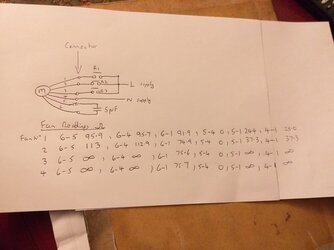
Here is the drawing: I have taken all measurements from the connector. To the right of the connector is PCB stuff, shown to help but these were not in cct when measurements taken.
All other readings between the 6 connections were infinity, that is greater than 1999 ohms on continuity. I have shown infinity readings for comparison with the other motors which had readings between the pins. 20200608_214856.jpg
 
Hmm. Fan 2 might possibly be operational on one speed only. The others all look pretty much FUBAR to me. 6-1 appears to be the aux winding which has the same resistance on fans 2, 3 & 4 so is probably OK on these. But fans 3 & 4 seem to have open-circuit main windings, as there is no continuity 4-1.

On fan 2, adding the resistances of 6-1 (aux, 74.9Ω) to 4-1 (main, 37.3Ω) gives 112.2Ω, which tallies with the reading 6-4 of 112.9Ω, so provided the main winding doesn't have shorted turns it stands a chance. We can't detect shorted turns here from resistance alone, as unlike the aux winding there are no others to compare it to, and two speed taps are O/C at the leadouts which could hide any shorted turns between the taps. But neither of the resistances of fan 1 match those of fan 2 and they don't add correctly, implying that there are shorts between the two windings. It's a bit odd that the aux winding appears high rather than low, but it's academic really.

The strangest thing is the lack of a circuit to either of the other speed taps on any of the fans. I could understand the PCB being populated with relays that are not connected when a single-speed motor is installed, but I've never knowingly seen a FHP motor with dummy leadouts that don't do anything. So why did those sections go O/C? I would be interested to see pics of the motor and board damage. I wonder whether multiple relays energised at once, shorting together the three speed taps? The winding will act like an autotransformer and pass a heavy current between the taps, which might be reflected in the position of the burnouts.
 
Last edited:
You are saying the readings between what we assume are speed taps were infinity yes?

So 1-2, 1-3, and 2-3 all show infinity on all motors, this would imply one of 2 things to me, they are not what you/we think they are or all motors are toast.

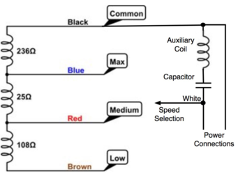
I assume this is what we are assuming it is -1591658067887.png

The L would be the L/H power connection and N - R/H but if this is the case then we are either assuming wrong or their is something definitely amiss.
Note this is off google so clearly example resistive values in there.
 
Last edited:
Thx, 20200606_11313.jpg20200606_20235.jpgbehaviour of the a/c units were as follows. A/C unit no1 - Fans 3 & 4, no fan action, system overheated and tripped out, PCB survived. I agree both these fans look dead.
A/C Unit No2 - Fans 1 and 2 appeared to have a delayed reaction as they should start when the compressor kicks in but they kicked in momentarily about 60 seconds late and then blew the PCB and tripped the breaker. Normally with A/C fans, they start slow and only when they cannot contain the temps do they go to high speed, if that still does not keep temps down the compressor drops out and the whole cycle starts again. I could not get my head around no readings from pins 2 and 3 to any other pins. I can check the PCBs to see if any relays have welded contacts.
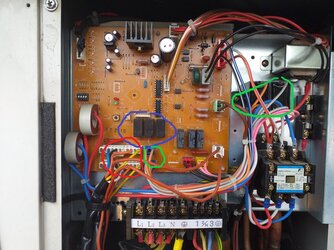
Top image i have highlighted relays (blue), caps (green) and fan connectors (red)
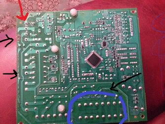
Bottom image i have highlighted fan connector pins (blue), burnt tracks (black) and power connector (red)
[automerge]1591658644[/automerge]
Stupid question; have you tried googling (or direct contacting) manufacturer for a schematic, should give you all the answers you seek
Yep, unit is old, tech support from manufacturer struggling, no schematic from internet, schematic on back of a/c unit shows fan as a black box.......
[automerge]1591659044[/automerge]
You are saying the readings between what we assume are speed taps were infinity yes?

So 1-2, 1-3, and 2-3 all show infinity on all motors, this would imply one of 2 things to me, they are not what you/we think they are or all motors are toast.

I assume this is what we are assuming it is -View attachment 58713

The L would be the L/H power connection and N - R/H but if this is the case then we are either assuming wrong or their is something definitely amiss.
Note this is off google so clearly example resistive values in there.
Agree, its normal to have fans with variable speed although on older ones this could be as per your diagram rather than inverter controlled. Yes no readings at all, i.e. max on continuity between pins 2 &3 to any other pin.
I suppose a quick answer is to measure a good one but thats a challenge at the moment.
 
Last edited:
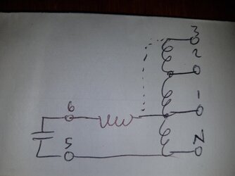
DW Going by the readings on fan 2, I think these motors have the aux winding commoned with tap 1 on the main (which, from the other leads being O/C we might assume is the nearest to N, although I've normally seen it done with the end of the winding as I've shown dotted).

This permutation makes the resistances of fan 2's winding, possibly the only one partly intact, add up correctly. Pic coming...
 
As Lucien points out, Fans 1 and 2 seem to have comparable readings in that although they differ the readings reflect the same pattern between pins so would suggest they are the good ones.
Our task is to reverse engineer the motor windings and contemplate it may not be as assumed.
 
15916594642332057567019777984477.jpg
Word word word
 
@Lucien Nunes What doesn't make sense and is common to all motors is the lack of a value between the 'taps' and also the Aux 6 to 2 or 3, in either of our diagrams it does not make sense that these are infinite on all of the fans.

Single phase not been something I deal with too often although I know the basic concepts I am just wondering whether these fans are specialised with some form of centrifugal switching in play which does the usual drop out of the starting cap' but possible also engages the 2 lower speeds to be used on demand.. this would explain the infinite reading on all the taps except full speed as the windings are not in circuit until they centrifugal switch has changed state.
 
Last edited:
I'm also puzzled by that, but I don't think there's anything as complicated as a centrifugal switch here, as it's clearly made down to a price and ordinary tapped PSC motors do an adequate job for multi-speed fans. The cap value looks typical for PSC run duty. I think the windings are just completely frazzled and perhaps the coil ends are stressed at the leadout joints and blow open when the rest of the winding shorts. Or perhaps the joints have corroded and gone open, even the main section of the main windings on 3 & 4 are open rather than short. I'm seeing this on some coils in cinema organ actions, where even in a perfectly dry environment, after 80 years the enamelled winding wire has corroded right through where there are flux residues near the solder joints.
 
It sounds like a good puzzling job, the kind that fire my neurons if I'm to be honest and I relish this kid of breakdown.

@plugsandsparks - it is a confusing case and please post any further developments or readings you find, if there are any legible plates on the motors here that would be a great help in trying to identify the motors and how they are wound.
 
Will photo the motor and ID plate. Also i think we all agree that fans 3 and 4 are dead and certainly that confirms what i observed. At the time i didn't realise these fans simply come on together as the modern 2 fan units control them independently.
I will have a go at opening up fan 3/4 and see what is inside. I can also check the board for poorly relays.
 
20200609_181206.jpg
Also i have looked at the relays and i have continuity across the relay that switches pin1 on the first PCB and on the other PCB i have continuity across the relay that switches pin 2.
Checking the relays R1 for pin 1 is std 5A capacity relay, R2 for Pin2 - they have used the high capacity version of the same relay type (10A) and R3 for Pin3 is a std 5A one again, all NO . So two poorly relays as well as burnt tracks,,,
 
Relays welded shut are consistent with the evidence so far. As I mentioned in #5, if two relays close at once (or one closes while another is welded) part of the main winding is shorted and the circulating current can exceed the supply current by transformer action. The impedance of the non-shorted section might be high enough not to blow the fuse at first, giving things a chance to overheat.
 
I've seen in at least one commercial design, and I'd do it that way myself, using changeover relays so that relay 1 applies power to one connection, only when relay 1 is off does it's NC contact pass power to relay 2, and similarly for power to relay 3. That way, barring an internal failure in a relay, it's impossible to cause the sort of "shorted section" fault described.
BTW, when running on fast (or to a lesser extent on medium) the the slow connection is typically at a significantly higher voltage than the mains supply - with the motor windings acting as an auto-transformer. I vaguely recall measuring over 400V to neutral on a a cooker hood fan motor.
 

Reply to 240V SP Ind Fan Motor wiring help in the Commercial Electrical Advice area at ElectriciansForums.net

Similar Threads

Looking for counsel / guidance to replace an original Dayton On/off with speed control switch. I’ve checked with a couple local electrical supply...
Replies
5
Views
631
1964 house old style wiring Need to wire a extractor fan up Is it possible to wire the extractor fan to report switch there's 2 red wires in the...
Replies
14
Views
911
Hi, I am installing a new bathroom fan. We had an electrician who ran 14/3 into a junction box. The black feeds a led light and the red was...
Replies
1
Views
663
L
WIRING FOR WALL SMART SWITCH FOR CEILING FAN/LIGHT Just bought a smart wall switch for a ceiling fan/light currently connected to a single switch...
Replies
0
Views
705
littletwinn
L
Hello, I currently have two switches in my bathroom. One controls the lights above the sink and the other controls a light above the toilet and...
Replies
0
Views
752

OFFICIAL SPONSORS

Electrical Goods - Electrical Tools - Brand Names Electrician Courses Green Electrical Goods PCB Way Electrical Goods - Electrical Tools - Brand Names Pushfit Wire Connectors Electric Underfloor Heating Electrician Courses
These Official Forum Sponsors May Provide Discounts to Regular Forum Members - If you would like to sponsor us then CLICK HERE and post a thread with who you are, and we'll send you some stats etc
This website was designed, optimised and is hosted by Untold Media. Operating under the name Untold Media since 2001.
Back
Top
AdBlock Detected

We get it, advertisements are annoying!

Sure, ad-blocking software does a great job at blocking ads, but it also blocks useful features of our website. For the best site experience please disable your AdBlocker.

I've Disabled AdBlock