B
You are using an out of date browser. It may not display this or other websites correctly.
You should upgrade or use an alternative browser.
You should upgrade or use an alternative browser.
S
Silly Sausage
iv been disconnecting at the MET end and then placing one probe on the pipe and the other on the disconnected cable.
That's the best way (I think) as it proves the clamp/pipe connection is good as well.
T
trev
I think the examiners know that a lot of us will not get A level english and so are prepared to cut some slack. That said, it is imperative to get certain terminology right eg it's is an insulation resistance tester not a megger. Call it the wrong thing and I guarantee you will duff a markWow, brilliant!! I'm taking my 2391 in september, there's so much info to work on. The main thing is that i'm a little worried about the written test....I ain't that good at doing essays, also perhaps getting the wording right for C&G standard, but that might just mean I need to read over and over again. Either way I'm looking forward to doing it, if I fail first time, it might give me a chance know what's involved. Thanks Bobby101, great help. :cool4:
Keep on wading through GN3 till you know it inside out and back to front mate, you'll be fine

B
brav
I think the examiners know that a lot of us will not get A level english and so are prepared to cut some slack. That said, it is imperative to get certain terminology right eg it's is an insulation resistance tester not a megger. Call it the wrong thing and I guarantee you will duff a mark
Keep on wading through GN3 till you know it inside out and back to front mate, you'll be fine
They've changed it to insulation resistance ohmmeter now :wink5:
T
trev
I'm an out of date dinosaur mate I still uses phases not linesThey've changed it to insulation resistance ohmmeter now :wink5:

B
brucelee
They've changed it to insulation resistance ohmmeter now :wink5:
yes mate it is wish someone would tell my tutors that i keep telling them same as low reading ohmmeter
and pscc tester and phase instead of line and live for the line also even though the neutral is also a live
direct and indirect contacts and they wonder why some of the students are struggling its even same on the course material and sample questions
fries my head i thought colleg was suposed to be the best route my experience is not and i have i had experience of all 3 routes lol
B
brav
I'm an out of date dinosaur mate I still uses phases not lines
Guess what, i forgot, they, the good folks who write gn3, have changed it back to insulation resistance tester, as per the new amendment in chapter 4. It was IR ohm meter in the red edition lol
B
brucelee
no way mate wish they would make there minds up
thanks for the heads up as i have jsut done 2330 302 and it was one of my questions
because of 2391 i learned insulaton resistance ohmeter
now back to IR tester they are getting money for old rope
thanks for the heads up as i have jsut done 2330 302 and it was one of my questions
because of 2391 i learned insulaton resistance ohmeter
now back to IR tester they are getting money for old rope
B
brav
no way mate wish they would make there minds up
thanks for the heads up as i have jsut done 2330 302 and it was one of my questions
because of 2391 i learned insulaton resistance ohmeter
now back to IR tester they are getting money for old rope
i was surprised they changed it as i thought IR ohmmeter made sense.
- Dec 9, 2010
- 7,461
- 817
- 1,688
- If you're a qualified, trainee, or retired electrician - Which country is it that your work will be / is / was aimed at?
- United Kingdom
- What type of forum member are you?
- Practising Electrician (Qualified - Domestic or Commercial etc)
some call it high range ohm meter, now them people are dinosaurs. but we all know what it means.
- Mar 11, 2010
- 688
- 77
- 1,203
- What type of forum member are you?
- Electrical Engineer (Qualified)
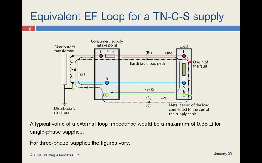
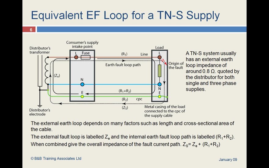
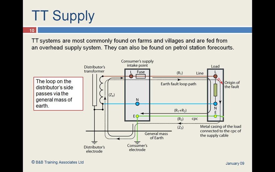
anyone got the diagrams for the earth fault paths, i think ive got it but would love to see the differences between TT ,TN-C-S, TNS
Cheers
Grand
Cheers
Grand
T
trev
N
NickS
Hi Grand, hope this helps, it's really rough but this was one of the first tasks we had to do in class of the systems. Also if you look in the On-Site Guide(red and green one) page 15 and 16, shows the physical connections of each of the system.
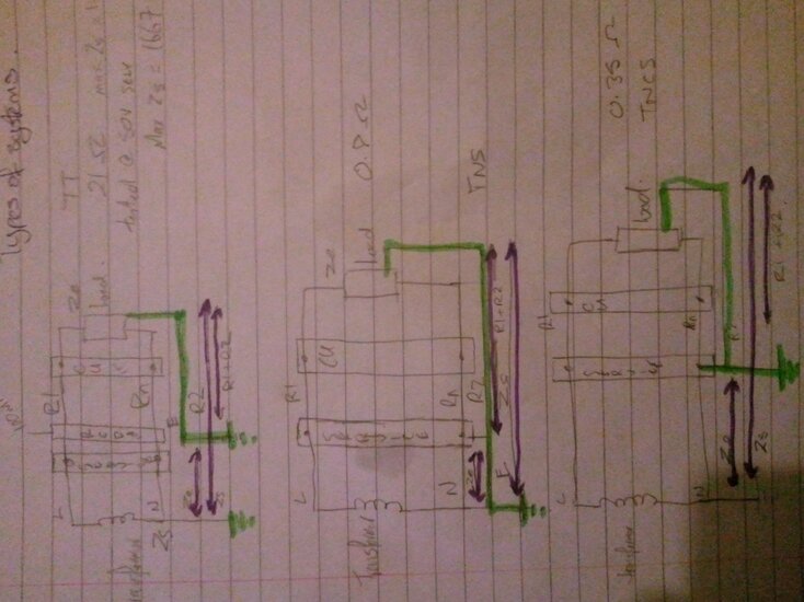
It kinda figured out that if you draw the normal circuit. ie showing the transformer, service cutout, CU and load, all you need then do is draw the earth path for each system because the actual circuit itself doesn't change, so you'll have three identical diagrams except for the earth path.
Hope this helps
Nick
S
SLSpark
N
N6rul
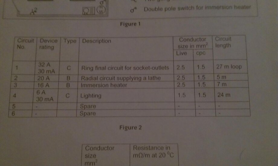
need help for 2394 exam question
Scenario
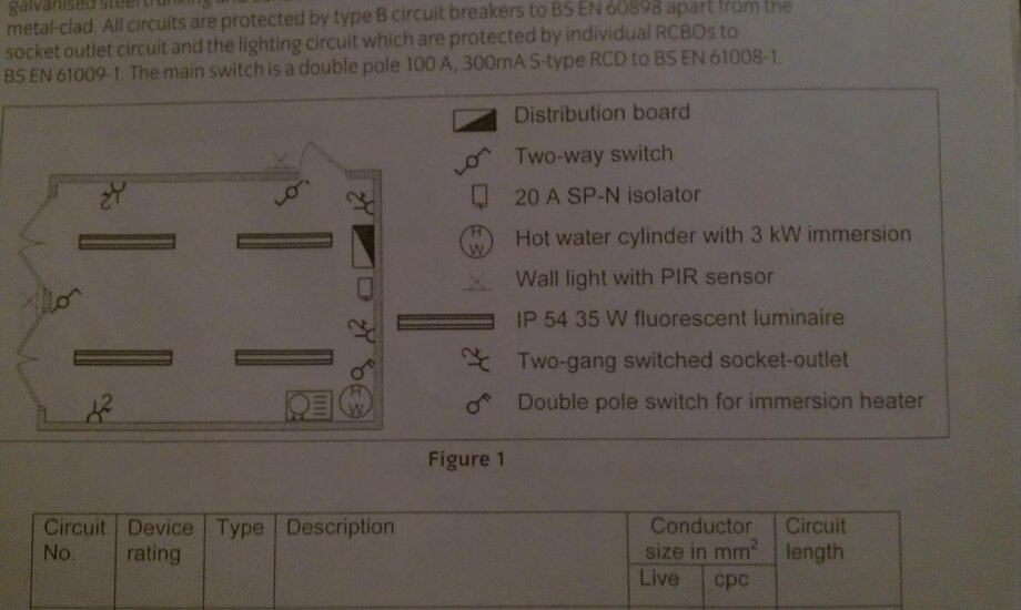
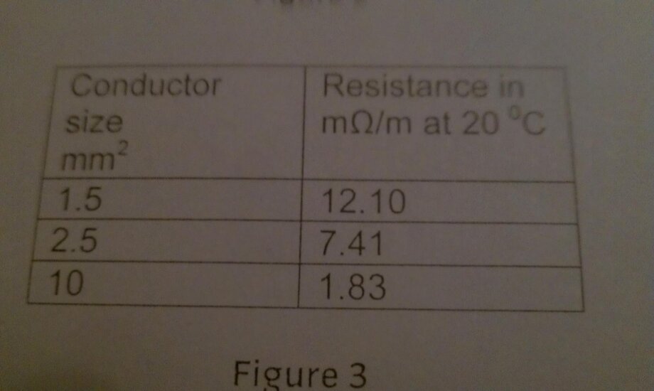
The building has its own supply and forms part of a 230 v TT System. Ze and PFC have not been measured. All circuits are wired in 70 degree Celsius thermoplastic single core cables, with copper conductors, in surface mounted, galvanized steel trunking and conduit. All accessories, including the distribution board, are metal clad. All circuits are protected by type B circuit breakers to BS EN 60898 Apart from the socket outlet circuit and the lighting circuit which are protected by individual RCBOs to BS EN 61009-1. the main switch is a double pole 100 A, 300 A S-type RCD to BS EN 61008-1.
PLEASE SEE ATTACHMENT FOR DIAGRAMS.
QUESTION 1
The ring final circuit is to be tested prior to connection to distribution board.
A) explain in detail how the continuity of ring circuit conductors test would be carried out.
B) determine the expected results for each stage.
C) a test of external loop impedance is to be carried out to assess the effectiveness of the earth electrode. Describe how this test is to be carried out after safe isolation of the installation has been complet.
Please can someone help. Thanks
Attachments
N
NickS
Hi N6rul, just a quick question for you. If you're at this stage in exams, shouldn't you already know how to answer those questions? .... just asking.
S
SPARTYKUS
Re: need help for 2394 exam question
I think you need to have a go first rather than just ask for "help". What are you thoughts?
If someone just writes out an answer, how is that in any way shape or form going to help you?
Man you gotta get stuck in! Have a go, scan your attempt in, and you will get reams of help (and it will be useful help, the only time you learn is when you get it wrong)
Scenario
The building has its own supply and forms part of a 230 v TT System. Ze and PFC have not been measured. All circuits are wired in 70 degree Celsius thermoplastic single core cables, with copper conductors, in surface mounted, galvanized steel trunking and conduit. All accessories, including the distribution board, are metal clad. All circuits are protected by type B circuit breakers to BS EN 60898 Apart from the socket outlet circuit and the lighting circuit which are protected by individual RCBOs to BS EN 61009-1. the main switch is a double pole 100 A, 300 A S-type RCD to BS EN 61008-1.
PLEASE SEE ATTACHMENT FOR DIAGRAMS.
QUESTION 1
The ring final circuit is to be tested prior to connection to distribution board.
A) explain in detail how the continuity of ring circuit conductors test would be carried out.
B) determine the expected results for each stage.
C) a test of external loop impedance is to be carried out to assess the effectiveness of the earth electrode. Describe how this test is to be carried out after safe isolation of the installation has been complet.
Please can someone help. Thanks
I think you need to have a go first rather than just ask for "help". What are you thoughts?
If someone just writes out an answer, how is that in any way shape or form going to help you?
Man you gotta get stuck in! Have a go, scan your attempt in, and you will get reams of help (and it will be useful help, the only time you learn is when you get it wrong)
S
SPARTYKUS
Similar threads
- Replies
- 4
- Views
- 212
- Question
- Replies
- 17
- Views
- 772
- Question
- Replies
- 23
- Views
- 831
- Replies
- 2
- Views
- 213
- Replies
- 8
- Views
- 543
- Replies
- 5
- Views
- 415
- Question
- Replies
- 2
- Views
- 2K
- Replies
- 9
- Views
- 2K
- Replies
- 3
- Views
- 758
- Replies
- 2
- Views
- 620
- Replies
- 1
- Views
- 1K
OFFICIAL SPONSORS


These Official Forum Sponsors May Provide Discounts to Regular Forum Members - If you would like to sponsor us then CLICK HERE and post a thread with who you are, and we'll send you some stats etc
Advert
Thread Information
- Title
- 2391 sum practical help
- Prefix
- N/A
- Replies
- 89


