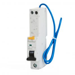
Discuss Another Hot tub install in the UK Electrical Forum area at ElectriciansForums.net

Gazthesparky

-
Arms
Reaction score
128
I have my tin hat on because I know this has been done to death and have read through a lot of the old posts.

I just wanted to run my proposal past a few of you and see if there is anything I have missed as its always good to get someone else's view.

Customer is needing a 32amp supply and hot tub company has said they require a 6mm supply with an isolator and flex left for them to connect.

My plan is to run a 10mm 3 core swa to a 40amp isolator from a new 2 way consumer unit Henley blocked from the tails. There is a Isolator on the current tails so will keep this and it will mean that there is one form of complete isolation. I have done the calculations and a 6mm will suffice with a volt drop of 11.2v so its on the borderline so hence going a larger size cable. It also allows for future proofing.

Now this is where it gets a bit messy. The supply to the property is PME. I intend to use the PME for the hot tub supply supplying it from a 32amp RCBO in the house. I am also intending to install an earth rod am I right in thinking that this gets installed at the hot tub end of the SWA? the idea is that should there be a PEN failure there is an earth path and the potential between the floating PEN earth and true earth is reduced as far as possible.

am I right in thinking that the rod does go at the hot tub end and not by the intake position of the property?

I am going to mount the isolator onto some uni strut installed into the ground. There is a fence panel 1 meter from the hot tub so too close to the tub. Also the fence doesn't seem too safe so I want to install my own support.

Finally they have also asked for a double socket by the tub again, I'm going to keep this 2 meters away from the tub. I am thinking of running a separate cable back to the house so this can be isolated as the customer is wanting to plug fairy lights in so the customer can switch them from the house. Im just wondering if i'm over complicating it though and should I just spur off the hot tub supply and install a fused spur and double socket

Thanks to any replys
 
If you are installing an electrode to supplement the existing PME then the electrode can be anywhere outside but to save on running cable, I’d install it as close to the point of entry (Where you drill the cable out) to the building as you can, so the run is short.
Obviously be weary of underground services like drainage etc.
 
Unless you get a really low Ra on your rods, you may just increase the step potential around the rod in the unlikely event of a lost neutral.
Why not just TT the hot tub and use the same earth system for the socket outlet as it will be in fairly close proximity? I would also opt for a DP RCD/RCBO personally.

I take it you are not commissioning the hot tub? What I have done in the past is supplied both pme and TT at the isolator, not connected the two together, and have marked each as such.
Put the ball in the court of the commissioning/installing company they can choose one or the other or choose to connect both together.
 
and locate the socket outlet at least 3m from tub. if numpty wants to plug in an extension, not your problem.
 
Unless you get a really low Ra on your rods, you may just increase the step potential around the rod in the unlikely event of a lost neutral.
Why not just TT the hot tub and use the same earth system for the socket outlet as it will be in fairly close proximity? I would also opt for a DP RCD/RCBO personally.

I take it you are not commissioning the hot tub? What I have done in the past is supplied both pme and TT at the isolator, not connected the two together, and have marked each as such.
Put the ball in the court of the commissioning/installing company they can choose one or the other or choose to connect both together.

that is a good idea providing both types of earthing but the written paperwork that has been provided to me by the customer from the hot tub company states that they do not provide any wiring and they require 5meters of flex left connected to the isolater. They just connect up the flex and if it’s not as requested then they charge for a return visit. So I get the feeling they are not interested what they have just as long as it looks like they normally have.

with regards to the DP RCBO I am going to go down that route but the customer is wanting another DB installing so they can fit a hob in the future as there current one is full so I was going to install a second consumer unit and use RCBOs.
I’m just not sure how these DP RCBOs fit do they need a separate enclosure or could I fit a consumer unit and cut the bus bar back and fit the DP RCBO at the end with a link from the neutral bar ?

The isolator will be at least 2 meters away from the tub and the socket 3 meters away.

I am still thinking of going down the supplementary rod road just incase the loss of a PEN conductor
 
I’m just not sure how these DP RCBOs fit do they need a separate enclosure or could I fit a consumer unit and cut the bus bar back and fit the DP RCBO at the end with a link from the neutral bar ?
A few of the normal CU single-wide RCBO are DP-switching, but only have the over-current trip on the phase side. I know the Wylex/Crabtree ones are like this and it helps for testing, etc, and someone mentioned that Fusebox ones might be.

Other full DP RCBO (i.e. they have over-current on both poles) might be OK as the end-of-busbar device, as you suggest, where the 2nd pole is then fed from a neutral wire link.
[automerge]1597649829[/automerge]
Just checked, the Fusebox RCBO are not DP switching so would be unsuitable for a TT style of supply isolation for an open PEN risk.
[automerge]1597650022[/automerge]
Also checked and it is the Crabtree 'Starbreaker' miniature that is DP switched, not the 'Loadstar' ones.
 
Last edited:
A few of the normal CU single-wide RCBO are DP-switching, but only have the over-current trip on the phase side. I know the Wylex/Crabtree ones are like this and it helps for testing, etc, and someone mentioned that Fusebox ones might be.

Other full DP RCBO (i.e. they have over-current on both poles) might be OK as the end-of-busbar device, as you suggest, where the 2nd pole is then fed from a neutral wire link.
[automerge]1597649829[/automerge]
Just checked, the Fusebox RCBO are not DP switching so would be unsuitable for a TT style of supply isolation for an open PEN risk.
[automerge]1597650022[/automerge]
Also checked and it is the Crabtree 'Starbreaker' miniature that is DP switched, not the 'Loadstar' ones.

Thanks for this

So basically its a double pole switching RCBO that I am requiring, has anyone got any other suggestions as to how install a DP RCBO whilst installing a new consumer unit for the customer to have a spare ways to future proof it

Also found this
32A Double Pole 2 Module C Curve 10kA 30mA Type AC RCBO - https://www.cef.co.uk/catalogue/products/921330
it says it is double pole switching so it switches the neutral.


Did also find this one From Fusebox single module and it appears that it is double pole switching maybe install a consumer unit with main switch and this rcbo leaving a few spare ways for other RCBOs
FuseBox RTAMB32 Miniature RCBO 32amp Double Pole A Type - https://www.gil-lec.co.uk/fusebox-rtamb32-mini-rcbo-32amp-a-type

cheers
 
Did also find this one From Fusebox single module and it appears that it is double pole switching maybe install a consumer unit with main switch and this rcbo leaving a few spare ways for other RCBOs
OK, so it looks like there are two types of Fusebox RCBOs as well! That one is DP switching, but this one (which I found earlier) is not:
[automerge]1597656760[/automerge]
I have never had one of the Fusebox CUs, etc, to play with but a few folk on here like them as the budget choice-to-go. They do reasonably priced CU with SPD as standard and, as it appears now, they have DP-switching RCBOs are a good price as well.

If you are happy with them just go for a Fusebox 2nd CU for the hot-tub with that DP RCBO and a few spare slots for anything else they need in the future.
 
Last edited:
OK, so it looks like there are two types of Fusebox RCBOs as well! That one is DP switching, but this one (which I found earlier) is not:
[automerge]1597656760[/automerge]
I have never had one of the Fusebox CUs, etc, to play with but a few folk on here like them as the budget choice-to-go. They do reasonably priced CU with SPD as standard and, as it appears now, they have DP-switching RCBOs are a good price as well.

If you are happy with them just go for a Fusebox 2nd CU for the hot-tub with that DP RCBO and a few spare slots for anything else they need in the future.

thanks PC1966 I wasn't having a pop regards the fusebox RCBO its just good to share knowledge of new products.

i'm probably going to go for the fusebox with an spd and the double pole switched RCBO
 
I am still thinking of going down the supplementary rod road just incase the loss of a PEN conductor

Would TT not be safer than a rod attached to the PME earth, as with TT there is no risk from open PEN conductor. And for the suplimentery rod to be of any use it would need to be around the 2 ohm mark (depending on the fault) which could be hard to achieve
 
Would TT not be safer than a rod attached to the PME earth, as with TT there is no risk from open PEN conductor. And for the suplimentery rod to be of any use it would need to be around the 2 ohm mark (depending on the fault) which could be hard to achieve


I get that but it seems silly to go to the effort of isolating the extremely efficient and low resistance PME earth path and solely relying on the fluctuating and higher earth rod path.

I know this is the big debate and can see both sides. If only we had something like a regulations book to give definitive answer lol

Failing that I scrap the rod idea and just use the PME and hope that there is never a PEN Failure.

My gut is telling me that although I need to achieve the 2 ohm mark on the rod to be successful it is better being there and providing some sort of earth path than not being

Im also going to install a DP RCBO so this will disconnect both live conductors should a fault occur.
 
I never understand this instruction from a hot tub installer.... “leave an isolator and 5m of flex“

so they want you to leave a connected flex, with bare ends, and the only protection is hoping no one turns on the isolator.
even padlocking it and leaving the key in the hands of a normal person (the customer) is questionable.

I know right I am planning to connect the flex up in an adaptable box and leaving the isolator switched off. That way I know the cable is terminated safely. My only concern is the hot tub company not liking it and trying to charge the customer for a return visit as they just want to see a coiled flex ready to go.

IMG_8656.JPG

This is the paperwork they provided to the customer even there so called example of the supply rough no glands on the isolator the SWA swooping and cable tied to a couple of brackets and the fact that they have left a coil of cable potentially live. this is how they are wanting the install to be left
 
These are double pole switching: Electrical Wholesaler - Hager RCBO 2P(1P+N) 6kA B-40A 30mA A Class AD940J - https://www.electricalwholesaler.ie/products/switchgearfuses/switchgeardistribution/rcboresidualcurrentbreakers/hagerrcdrccb2p40a30maaclassad940j. All the double pole switching units that are definitely double pole are two module wide, all those that say they are and are only one module wide on investigation are not.
What about the Wylex NHX miniature rcbo's, it's a switched neutral.
Wylex rcbo.jpg
 
Last edited:
I am surprised that Wylex have been able to produce a switched neutral RCBO in a single module, what surprise's me mostly is that if and I emphasise the if they are able to achieve a 3mm air gap (unverified) on both the phase and neutral in that space I would like to see how they do it, because that is what is required under EU specifications.

Can't find a single module DP RCBO tear down, but here's one of the Crabtree/Wylex single module RCBO/AFDD which crams even more into the same space.

View: https://www.youtube.com/watch?v=gdVntVfP6Q8
 
Thanks for digging that out, to me it only shows the phase being coil controlled by the large coil on the back of the unit, the smaller wire coil and toroidal unit controlling the arc disconnection, by my estimation to be a truly dual pole breaker there would have to be two large coils controlling the phase and neutral independently, supposition on my part, but that's where I was coming from in my previous post when I posted that the unit needing to be two module in width, there have been lots of claims of dual RCBO's prior to this point, but as I posted above they need to separate the contacts by 3mm to conform to the EU standard, I certainly look forward to someone finding one, as I have run out of room in my CU.
[automerge]1597705509[/automerge]
Difficult to see the circuit diagram on the side of the FuseBox RTAMB, but it does look as though it is double switched, by one coil, would be interested in the separation gap of the contacts, I will try to contact them tomorrow.
 
Last edited:
I've attached the data sheet for that Fusebox RCBO, which shows its circuit diagram.

It's interesting that Crabtree, Wylex & Fusebox label these RCBOs as 1P+N, but they're often advertised by wholesalers (who should know better) as DP.

My initial interest in this type of breaker stemmed from trying to find something that would offer additional fault protection on a TT system and settled on Crabtree, due to Starbreaker's main switch being on the left side. I was happy that these switched both poles in an overcurrent situation, but hadn't thought much beyond that. Combined with a time delayed upstream RCD, they're certainly better than what was replaced.
 

Attachments

  • fusebox_technical_data_sheet_rt063230b_1.pdf
    227.5 KB · Views: 13
I've attached the data sheet for that Fusebox RCBO, which shows its circuit diagram.

Well that one certainly only shows the phase being switched and is denoted as 1P+N will assume it's not the new compact RTAMB type except that is the only Fusebox RCBO data sheet I can find also.

Even the Crabtree Starbreaker is denoted as 1P+N on it's data sheet, it makes me wonder if the N is electronically disconnected and not a physical 3mm separation.

 
Last edited:
Agreed, but on the circuit diagram/s they only show one physical disconnection.

I just looked at the Hager two module RCBO data sheet and that says 1P+N, but N switched concurrently, could only find it on an African site, will look for a EU data sheet to see if it's different: https://www.africa.hager.com/bs/files/download/0/78809_1/0/AD906J_Data_Sheet.pdf

Found an Irish site with the data sheet on, but that shows even less information: https://www.hager.ie/files/download/0/559125_1/0/AD906J_Data_Sheet.pdf
 
Last edited:
but as I posted above they need to separate the contacts by 3mm to conform to the EU standard
At around 8:30 in that video you can see the neutral contacts is open by at least 3mm (more or less central to the picture). Only later in the video when they flip it over you see the thermal-magnetic trip side that opens the line and has the arc chamber.

Most likely it is based on the typical "switched neutral" style of switch where N makes first/breaks last compared to the line contact(s) so does not have to switch the majority of current (hence no arc chute).
 
Got hold of a Hagar AD906J an it shows a physical disconnection of both poles on the diagram on the front of the unit whereas most single module units show a pass through of the N.
DSC02002.jpeg
 
Except the Wylex/Crabtree/Fusebox units do not show a physical disconnection of the N as they do for the line on their data sheets, so I am dubious that the N is switched, as I have said before, the physical size of the compact units may not be able to accommodate two switch units, it is supposition on my part as you say without taking a Hager unit apart it's difficult to say categorically, but I do think the diagram may be indicative of the units parameters.

All seems a bit strange to me, if these units are 2p switched why don't they just say so instead of 1P+N?
[automerge]1597738797[/automerge]
Thinking about the previous question, I wonder if the difference is that the N does not have it's own fault circuit and is just dragged along with the line if a fault develops?

I think that is what N switched concurrently is supposed to mean, Hmmm
 
Last edited:
Except the Wylex/Crabtree/Fusebox units do not show a physical disconnection of the N as they do for the line on their data sheets, so I am dubious that the N is switched,
But they do:
IMG_20200818_092205276.jpg


All seems a bit strange to me, if these units are 2p switched why don't they just say so instead of 1P+N?

Thinking about the previous question, I wonder if the difference is that the N does not have it's own fault circuit and is just dragged along with the line if a fault develops?
Exactly. N is switched, it is not tripping on an over-current fault alone. There is only 1 pole that is capable of sensing and fully interrupting the fault current.

In the diagram from Wylex you see the 'X' for the thermal trip is only on the L path ("LOAD 2" as they call it).
[automerge]1597739699[/automerge]
Of course, as an RCBO if you do have a fault leading to N-E current it will trip.

But it would not be pretty if you had reversed polarity fault AND then a 'N' to E fault in the kA range!
 
Last edited:
that is a good idea providing both types of earthing but the written paperwork that has been provided to me by the customer from the hot tub company states that they do not provide any wiring and they require 5meters of flex left connected to the isolater. They just connect up the flex and if it’s not as requested then they charge for a return visit. So I get the feeling they are not interested what they have just as long as it looks like they normally have.

with regards to the DP RCBO I am going to go down that route but the customer is wanting another DB installing so they can fit a hob in the future as there current one is full so I was going to install a second consumer unit and use RCBOs.
I’m just not sure how these DP RCBOs fit do they need a separate enclosure or could I fit a consumer unit and cut the bus bar back and fit the DP RCBO at the end with a link from the neutral bar ?

The isolator will be at least 2 meters away from the tub and the socket 3 meters away.

I am still thinking of going down the supplementary rod road just incase the loss of a PEN conductor
I have just started a thread which has some similarities to this thread with regards the earthing. See in particular post 3 Understanding the relationship between TNCS, TNS and TT - https://www.electriciansforums.net/threads/understanding-the-relationship-between-tncs-tns-and-tt.188980/

It would seem that if you are going to extend the PME AND add an earth rod for the Hot tub you could well be making it more dangerous in the event of PEN failure. Unless of course you did get the Ra down to around 2 ohm (which isn't going to happen).

I have to admit I find it a bit confusing but if you Just made the new CU a TT and did not extend the PME then the new earth rod would not raise to 230V in the event of a PEN failure which seems like a better option!

If you TT the new install and don't extend the PME you rely solely on the RCD for fault protection.

If you extend the PME you have ADS and additional protection with an RCD but in the event of PEN it could become dangerous.

I think I would go for option one, TT for the new install. I'd probably run a 3 core 10mm SWA (and isolate the armour and 3rd core) in case I changed my mind!
 
I thought I understood this subject some time back, but this thread has got me confused again.

What is the point of using a DP or SP & Switched Neutral RCBO for this hot tub supply & PEN conductor faults, if it was TT'd? Other than manufactures (i.e. Schneider) or disconnecting neutral for fault finding etc.

Where is this hot tub being installed, on what surface is it being placed? I recall reading a thread about faulty Lazy Spa hot tub, with voltages on the water, but all of these hot tubs are insulated, no metal surfaces. Not as if its like a ev car. If the bathers not stepping on bare Earth, would it not be better to rely on the PME, and not to be too concerned about a lost PEN conductor?
 
pme is acceptable as is a SP rcbo, but nothing wrong with a belt and braces approach. Lost PEN may be quite rare but it still happens.
Iv'e always adopted the idea of treating a hot tub as a swimming pool.

Drifting slightly off the subject, it is strange that if you have a shower in a bedroom that a socket outlet requires to be no less than 3 metres away. However, with a swimming pool where it is not physically possible to locate a socket outside of zone 1, then it will be allowed 1.25mts horizontally from zone 0???
[automerge]1597769883[/automerge]
I missed part of your post. If a PEN fault occurs, then with a SP rcbo, this will still allow a path through the hot tub element/pump via the faulty neutral will it not?
 
Last edited:
pme is acceptable as is a SP rcbo, but nothing wrong with a belt and braces approach. Lost PEN may be quite rare but it still happens.
Iv'e always adopted the idea of treating a hot tub as a swimming pool.

Drifting slightly off the subject, it is strange that if you have a shower in a bedroom that a socket outlet requires to be no less than 3 metres away. However, with a swimming pool where it is not physically possible to locate a socket outside of zone 1, then it will be allowed 1.25mts horizontally from zone 0???
[automerge]1597769883[/automerge]
I missed part of your post. If a PEN fault occurs, then with a SP rcbo, this will still allow a path through the hot tub element/pump via the faulty neutral will it not?

I‘m not to familiar with hot tub designs, I would seek guidance from the manufacturer.

However, the point of lost pen conductor, and using a SP or DP device, would not make much difference surly, as both would still be energised during this situation. In this situation in is the still connected exposed conductive parts, extraneous conductive parts and true Earth, that’s cause for concern, not the broken neutral.

Section 702 does not preclude the use of pme for swimming pools.

Most hot tubs I’ve seen have no exposed or extraneous conductive parts. As said, I’m not sure of the internal components design,.
 
However, the point of lost pen conductor, and using a SP or DP device, would not make much difference surly, as both would still be energised during this situation. In this situation in is the still connected exposed conductive parts, extraneous conductive parts and true Earth, that’s cause for concern, not the broken neutral.
.
I agree. there is no guarantee that an rcd/rcbo would trip in such a circumstance, but my ideology is just to be able to provide total isolation, hence TT to isolate from the pme and DP to ensure total isolation of the supply.


You are correct also about pme not being precluded with swimming pools, but again that's something I would not do.
 
In the TN case from PME then a DP breaker is not really an advantage here - if your PEN goes live your hot tub earth, etc, is still live with L & N open anyway.

But in the case of going TT to avoid the PEN fault risk you really must be DP breaking otherwise a 'live N' style of fault arising from the PME fault would not be isolated by the breaker opening.
[automerge]1597824312[/automerge]
Just to add the RCBO would not open on a PME fault alone, but if you had another fault leading to earth leakage current at the same time (e.g. rise in L-true E volts causing breakdown, etc) you would still expect it to be safely disconnected.
 
Somehow, I think, if it were a seriously regular occurrence, the supply authorities might be under a great deal of pressure to 'get it sorted'.
It is, after all, their duty.
In all fairness, every supply earthing problem I've reported has resulted in a same day visit.
 
All true, but I was trying to get to the bottom of how many Electricians on this Forum have had first hand experience of a PME fault, personally I have never found or had to deal with one!
 
All true, but I was trying to get to the bottom of how many Electricians on this Forum have had first hand experience of a PME fault, personally I have never found or had to deal with one!
I think even if @pc1966 had said he had never come across a PEN break that would not really mean they do not exist. It would neither suggest they were common or rare. You would need to ask perhaps 1000 electricians across varying locations, then perhaps you could form a statistical judgement.... but not on a population of 1.
Why not start a poll, it would be interesting.
 
I started a thread about this sort of thing here:
From the comments there it seems to be related to water ingress in joints in aluminium waveform cables, etc, so how likely you are to see it would depend on you being in a region with old-ish TN-C-S supplies. It does make the news occasionally when someone gets hurt:
 
Last edited:
I think even if @pc1966 had said he had never come across a PEN break that would not really mean they do not exist. It would neither suggest they were common or rare. You would need to ask perhaps 1000 electricians across varying locations, then perhaps you could form a statistical judgement.... but not on a population of 1.
Why not start a poll, it would be interesting.

I never suggested they did not exist and asked the question of how many Electricians on here have experienced a PEN break, I did not ask a population of 1.
 
So are we now reached the conclusion that I should isolate the PME supply on the hot tub supply and the socket and TT the 2 supplies. Keeping the house PME

my next issue I have is that the customeris wanting an extra consumer unit put in so they can add a hob in the future if I TT my new one there will be 2 earthing systems in the property.

Should I then install 2 consumer units one for the hot tub supply/socket (TT) and one for the future hob PME

means buying 2 units and 2SPDs

or installing 1 new unit and running PME sub main to hot tub and isolating the earth and installing an Earth rod at the hot tub
Only issue with that is how to Earth the socket too the same Rod
 
So are we now reached the conclusion that I should isolate the PME supply on the hot tub supply and the socket and TT the 2 supplies. Keeping the house PME

my next issue I have is that the customer is wanting an extra consumer unit put in so they can add a hob in the future if I TT my new one there will be 2 earthing systems in the property.

Should I then install 2 consumer units one for the hot tub supply/socket (TT) and one for the future hob PME

means buying 2 units and 2SPDs

or installing 1 new unit and running PME sub main to hot tub and isolating the earth and installing an Earth rod at the hot tub
Only issue with that is how to Earth the socket too the same Rod
If the proposed CU change is likely to happen before the hot tub installation you are best simply to put in one big enough CU for the lot and keep the house on PME. Single SPD, single isolation switch, everything consistent.

If you can run SWA out to the hot tub you have the option to simply feed it from a MCB and put the RCD out there in an IP65 or similar enclosure (as for caravan feed, etc) and have all that is down-stream of the RCD on a local TT earth rod.

Or if it is easier and your CU choice has DP RCBO then all you need at the hot tub end is the isolator and to separate the SWA earth (from the PME supply) from the outdoor circuits' TT earth. So use a plastic gland, etc, and not the usual metal type for connecting the armour up.

If the sockets are not expected to be used for large loads or extended in the future, then just put them on the same 32A supply as the hot tub. That way you don't risk a PME-derived earth to a lamp or similar being next to a good true-Earth TT supply.

Others might have some better ideas!
 

Reply to Another Hot tub install in the UK Electrical Forum area at ElectriciansForums.net

Similar Threads

Evening everyone . Currently looking at pricing a job up . It’s a hot tub supply . Outside socket with a few spare ways in an outdoor cu . 10mm...
Replies
7
Views
690
The earthing arrangement where the hot tub will be installed is formed in the TN-C-S system. I want to install the sub-main distribution circuit...
Replies
18
Views
2K
I have someone that wants a hot tub installing and it’ll be my first time, I have came up with anxixeaxfwanted to check it was correct. I wanted...
Replies
10
Views
1K
Replaced our old 240v hot tub with a new one, which also uses 240v for motors, heater, etc, and 120v for low amp LEDs and touch screen control...
Replies
4
Views
1K
Hi Guys So I've never installed a hot tub supply before so take it easy on me. I've spent a bit of time researching it myself and its a minefield...
Replies
7
Views
2K

OFFICIAL SPONSORS

Electrical Goods - Electrical Tools - Brand Names Electrician Courses Green Electrical Goods PCB Way Electrical Goods - Electrical Tools - Brand Names Pushfit Wire Connectors Electric Underfloor Heating Electrician Courses
These Official Forum Sponsors May Provide Discounts to Regular Forum Members - If you would like to sponsor us then CLICK HERE and post a thread with who you are, and we'll send you some stats etc

YOUR Unread Posts

This website was designed, optimised and is hosted by untold.media Operating under the name Untold Media since 2001.
Back
Top
AdBlock Detected

We get it, advertisements are annoying!

Sure, ad-blocking software does a great job at blocking ads, but it also blocks useful features of our website. For the best site experience please disable your AdBlocker.

I've Disabled AdBlock