Discuss Honeywell AT175F Wiring Help in the UK Electrical Forum area at ElectriciansForums.net

I just checked and did not get continuity between either secondary lead and the transformer mount frame.

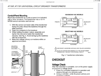
Without knowing the grounded side... here where I am now.

I just completed doing some rewiring of my thermostats. Whomever wired this did the following:

(1) Upstairs Tstat - connected to system via a single 3-wire conductor
(2) Garage and Living Room - connected to system via a shared single 3-wire, where W was common to all and connected to one side of the TF, and Blue was used by one Tstat and Red by the other (i.e., the conductor ran through one thermostat and terminated on the other) both of which ran through the respective Zone Valve, terminating back on the other side of the transformer.
(3) Downstairs and Master BR - same as #2, running throught the downstairs tstat. Wire color scheme was consistent.

Result was that I only had one zone with a complete 3-wire run, the Upstairs. I noticed that I could easily reach the downstairs and garage thermostats from the crawlspace, so I ran two additional 3-wire conductors to each of those, and removed those tstats from the runs that terminated in the Living Room and Master BR, freeing up the 3rd wire in the other two. Now I have 3-wire conductors running to all 5 zones. I have one of the new smart tstats I'm testing for a company that I am going to hook up.

I think I now have what I need, but I'm waiting on a response from the company because I'm not sure if the tstat is looking for 24VAC power across R-C or W-C. I assume R-C, but they labeled 'R' in their manual as 24VAC RETURN. It probably doesn't matter, but one of the two (R or W) is connected directly to one side of the transformer, and the other is connected to the Zone Valve motor (which I believe is typically W).

Now, in the case of R being connected to the transformer, and W to the Zone Valve, my thinking is that I would connect my C from the tstat to the transformer side of the Zone Valve motor lead (the OTHER yellow lead). As I proposed before, that would give me a continuous flow of 24VAC whether the tstat was calling for heat or not. I'm just waiting to hear which tstat terminal needs to go directly to the transformer. If any of that sounds off, please let me know.

You guys have been very helpful. Thank you for your help and responses.

Cheers!
Also just realized something you said. This transformer dose not have an internal ground, This would be a external grounding. One of the secondary wires to ground from line (typical for 24v AC transformer in a furnace). For this application it is not necessary to have a ground.
 
Great! Thanks guys. Based upon your comments, insight, and feedback, I think I'm OK to move forward with my original plan. Notwithstanding the wiring color confusion in my installation, now that I understand HOW it's wired, I can move forward to installing the smart stat with the wiring for C that I described earlier, but which is much better illustrated in the modified image below. My smart stat comes with RH and RC jumpered by default (for single transformer systems, which mine is), and labeled the connectors as 24RH, 24C and 24RC (plus others), which indicates that I wire my transformer across the 24C and 24RH for 24Vac power - blue to 24C, the other two to 24RH and W1. Other wire colors notwithstanding, I will wire the blue C wire as shown below. Thank you for your help.

zones.gif
 
Great! Thanks guys. Based upon your comments, insight, and feedback, I think I'm OK to move forward with my original plan. Notwithstanding the wiring color confusion in my installation, now that I understand HOW it's wired, I can move forward to installing the smart stat with the wiring for C that I described earlier, but which is much better illustrated in the modified image below. My smart stat comes with RH and RC jumpered by default (for single transformer systems, which mine is), and labeled the connectors as 24RH, 24C and 24RC (plus others), which indicates that I wire my transformer across the 24C and 24RH for 24Vac power - blue to 24C, the other two to 24RH and W1. Other wire colors notwithstanding, I will wire the blue C wire as shown below. Thank you for your help.

View attachment 92020
That looks correct!!
 

Reply to Honeywell AT175F Wiring Help in the UK Electrical Forum area at ElectriciansForums.net

Similar Threads

For the past few years, I have used a hydronic system (outdoor wood boiler) with both high and low temp working simultaneously. The low temp...
Replies
6
Views
794
Hi, I installed 6 recessed lights in my living room. I’m now up to the wiring part of the project. There is an outlet in the room that is...
Replies
1
Views
482
I’ve got the following setup on the stairway (picture included) https://pasteboard.co/15IoYrvn2VgA.webp https://pasteboard.co/2UzMaHCbs1iE.webp...
Replies
3
Views
778
Hello everyone, hope all are well. I'm changing a ceiling rose and have lost the diagram showing where everything was connected (to the old light)...
Replies
8
Views
959
I have pulled out an old evaporative system I purchased many years ago from storage to have a look at it and see if I can get it running. Was...
Replies
1
Views
227

OFFICIAL SPONSORS

Electrical Goods - Electrical Tools - Brand Names Electrician Courses Green Electrical Goods PCB Way Electrical Goods - Electrical Tools - Brand Names Pushfit Wire Connectors Electric Underfloor Heating Electrician Courses
These Official Forum Sponsors May Provide Discounts to Regular Forum Members - If you would like to sponsor us then CLICK HERE and post a thread with who you are, and we'll send you some stats etc

YOUR Unread Posts

This website was designed, optimised and is hosted by untold.media Operating under the name Untold Media since 2001.
Back
Top