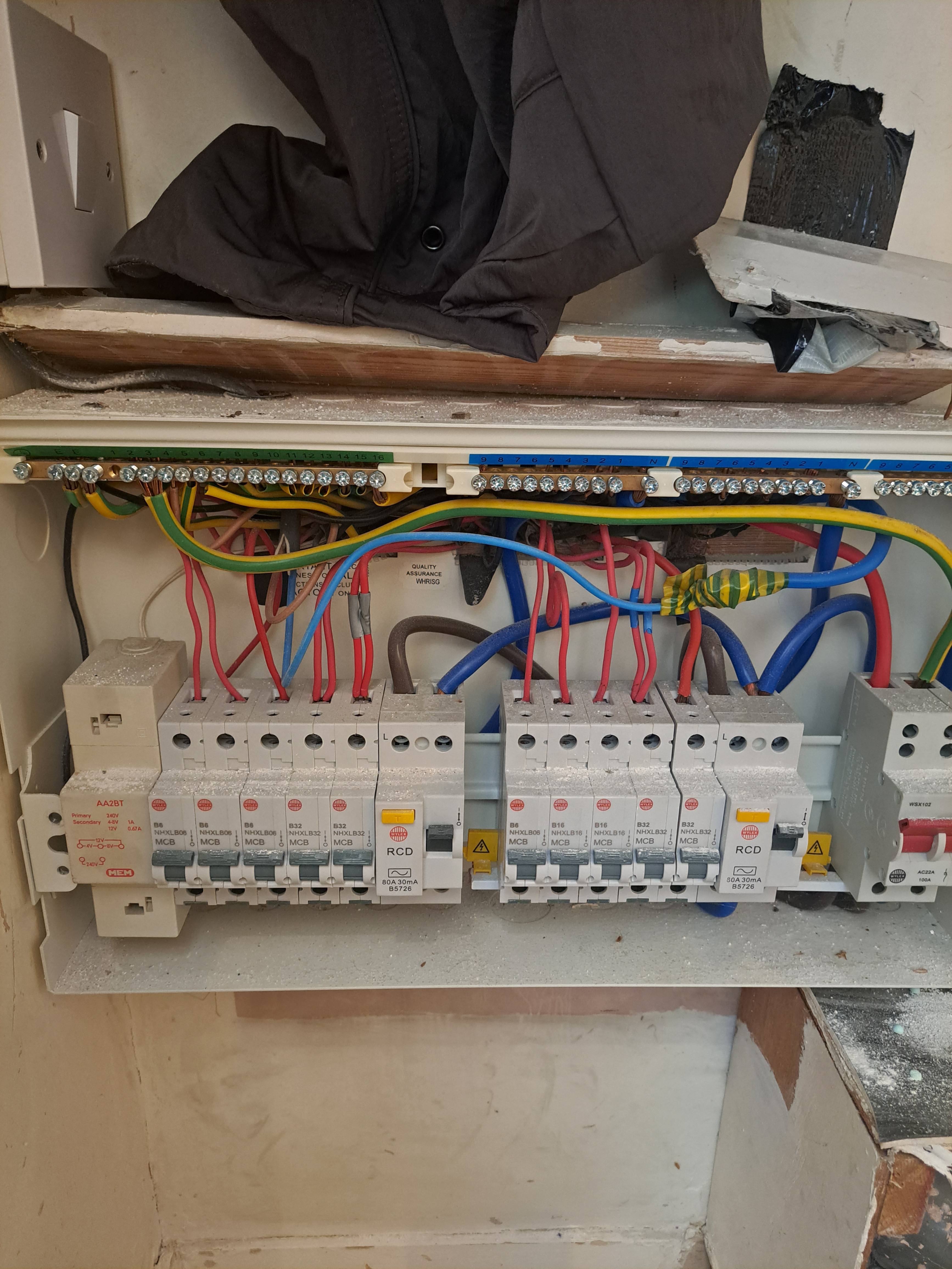

Came across this setup today, upon further investigation i noticed the distributors neutral terminal completly slackened off in the meter (looked intentional) is this to prevent any possible current from returning via the meter?
With the 1g switch (just above DB) turned on the meter would read like normal. With the switch off the meter has no neutral and therfore is blank.


