D

Designmen90

Hello everyone!

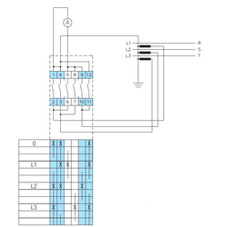
I have problem with ammeter switch from attachment. Here is connection diagram, and everything looks fine. But, if we look carefully, we will see that ground and L3 are short connected via 3-4 terminals, when we put switch in L1 position. So, my question is, how it's possible, it looks like short-circuit?
 

Attachments

  • Ammeter switch.png
    Ammeter switch.png
    27.2 KB · Views: 85
Hello everyone!

I have problem with ammeter switch from attachment. Here is connection diagram, and everything looks fine. But, if we look carefully, we will see that ground and L3 are short connected via 3-4 terminals, when we put switch in L1 position. So, my question is, how it's possible, it looks like short-circuit?
Looks correct to me.

When it's
in o each ct is shorted direct to the star point,
In L1, L1 passes through the ammeter, L2, and L3 are shorted direct to the star point,
In L2, L2 passes through the ammeter, L1, and L3 are shorted direct to the star point,
In L3, L3 passes through the ammeter, L1, and L2 are shorted direct to the star point.

Which is what you want.
 
  • Like
Reactions: Designmen90
Looks correct to me.

When it's
in o each ct is shorted direct to the star point,
In L1, L1 passes through the ammeter, L2, and L3 are shorted direct to the star point,
In L2, L2 passes through the ammeter, L1, and L3 are shorted direct to the star point,
In L3, L3 passes through the ammeter, L1, and L2 are shorted direct to the star point.

Which is what you want.
Agree
 
The crucial point here being that the secondary of a current transformer should never be left open-circuit, as a high voltage can be developed across it. This is true generally of current sources: short = OK, open = bad, opposite of voltage sources. Each transformer must either be connected to the ammeter or shorted, and the switch cams must be of the make-before-break type so that there is no open-circuit moment as the switch position is changed.
 
The crucial point here being that the secondary of a current transformer should never be left open-circuit, as a high voltage can be developed across it. This is true generally of current sources: short = OK, open = bad, opposite of voltage sources. Each transformer must either be connected to the ammeter or shorted, and the switch cams must be of the make-before-break type so that there is no open-circuit moment as the switch position is changed.
Correct, that's why there are so many poles on the switch, when it looks like you could achieve the same with just 3.

I suppose people could also miss the details in the switch sequence drawing, it clearly shows overlap in the operation.
 
  • Like
Reactions: pc1966

Similar threads

OFFICIAL SPONSORS

Electrical Goods - Electrical Tools - Brand Names Electrician Courses Green Electrical Goods PCB Way Electric Underfloor Heating Electrician Courses Heating 2 Go Electrician Workwear Supplier
These Official Forum Sponsors May Provide Discounts to Regular Forum Members - If you would like to sponsor us then CLICK HERE and post a thread with who you are, and we'll send you some stats etc

Advert

Daily, weekly or monthly email

Thread Information

Title
Ammeter switch connection
Prefix
N/A
Forum
UK Electrical Forum
Start date
Last reply date
Replies
4

Advert

Thread statistics

Created
Designmen90,
Last reply from
Julie.,
Replies
4
Views
1,623

Advert