Discuss Brew panel in the UK Electrical Forum area at ElectriciansForums.net

Reaction score
9
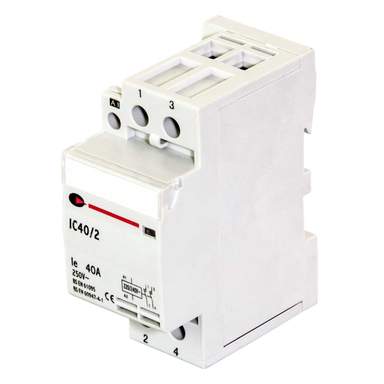
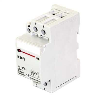
I built a panel for brewing and tried it out yesterday, it's is designed to power a 6kw element in a a 70 litre stainless kettle. It ran great doing a 66 degree mash controlled by the PID for 60 minutes, all other controls like pump control, amp and flow meters ran like a dream. When I stepped up to 100 degrees I could smell burning then the trip switch went. The burning was the coil relays (from China) melting. I have two SSR's fitting with each having a heat sink, I fitted a PC cooling fan on the element heat sink. Could this have caused an issue? I have been told to replace the coil relays with 2 pole 40 amp contactor 240V, will this solve my issue. I have attached my wiring diagram does it look right and how would I rewire the new contactors? Any advice would be greatly appreciated!
 

Attachments

  • HOW.jpg
    100.8 KB · Views: 81
A quick look at your diagram shows an odd lack of connection between the incoming neutral and the lower of the two terminal strips, is that true?!

If the relays coil is hot/burning most likely it is faulty manufacture, incorrectly labelled (e.g. 110V coil sold as 230V), or simply crap. Replacing them with contactors of known quality should fix things.

If the cause of the over heating is the relay contacts then much the same applies - they were poor quality or very old stock and tarnished/high resistance when first used so able to heat up under load. Generally that sort of thing tends to runaway as heat can further tarnish the contacts, etc.

Finally I guess the enclosure for all of the electrics is kept sensibly cool (i.e. not heated to 70C or so)?
[automerge]1586784983[/automerge]
One final point, that fuse holder illustrated in your diagram looks like the sort you get for automotive electrics and almost certainly is not rated for mains use!

Related to that any fuse used for mains work must be rated for that, i.e. a High Rupture Capacity (HRC) fuse with a ceramic body. Glass one can explode under fault conditions when hundreds or thousands of amps flow and start fires if the holder is not flame proof!
 
Sorry not sure what you are pointing out regarding the neutrals? The diagram I used is from the electric brewery website , that's the fuse holder they sell. I have a digital temperature readout on the panel to read internal temp.
 
Those are USA style connectors, not sure if they would be approved for use in the UK, so I'm guess this all came from America?

But given that, are you quite sure they sent you 230V relays and not 110V ones?

Also what rating is the fuse holder? Did it come with a ceramic fuse?
[automerge]1586786925[/automerge]
For the neutral I would expect a link from pin 2 of the power relay (where the AC neutral comes in) to the lower terminal strip where the neutrals of the relay coils, etc, are joined.
[automerge]1586787448[/automerge]
Given the 6kW rating for the heater that is pretty close to 30A so next typical size of contactor would be 40A like this one:

 
Last edited:
Are the relay coils marked for 220V ac? If so they are then they are unsuitable for use in the UK with its 240V ac mains (forget 230V as a figure). A 220V ac coil will run hot on 240V and eventually overheat and destroy itself.
 
Running a 220V coil at 253V (upper limit of UK mains) is only 32% more heat and that is not going to melt it in an hour of operation. My suspicion is they are simply not up to the job of switching a 6kW heater, irrespective of what they say on the label!

Some decent 40A contactors should solve the problem.
 
Having had relays of dubious brand melt on you I don't really think very cheap eBay products could be recommended!

These are the same part number as CEF but significantly cheaper (photo seems not to match):
Cheaper but no indication of stock levels or delivery times, etc:
Generally speaking for a 40A contactor anything less than £20 is surprisingly cheap. If you wanted something to just work and last a long time then you probably would go for Schneider and their ones are listed at around £60
[automerge]1586798692[/automerge]
For example:
 
Mark Stewart - could you amplify please what you said in #1:
The burning was the coil relays (from China) melting.

What part(s) of the relay was/were burning? How did the relay fail - the contacts or the coil or both? - some pictures would be welcome for me to pore over.

Chinarelay do a 240V ac version of that coil - interestingly its coil resistance is increased to 8060 Ohms; the 220V ac one has a coil resistance of 6770 Ohms. I wonder why? ;-)
 
Last edited:
It certainly looks like a current shunt.

Also there are a surprising number of cable so that relay! I really doubt it is the coil, I think it is the contacts that have burned under a 26A or so load.
 
Mark Stewart: Can we have a photo of the relay bottom and with its cover off?

I agree this relay is not adequately rated to switch and pass 30A for long periods - so you need something with a higher ac resistive load rating - of the order 40A.

I stand by my earlier remarks on the ac voltage (and frequency) rating of the coil.

What is the voltage rating of the heating element ? Perhaps a photo of the data plate?
 
Last edited:
The burn mark is in an odd place, if the contacts were overheating I would almost expect the melting around the pins a bit more rather than the centre. Have you popped the cover off the burnt relay to see inside yet? What wiring diagram are you following as the one you posted has no mention of a current shunt?
 
I have looked at the electric brewery web site in the USA. The current shunt is there so that at a later date an ammeter or current monitor can be added into the control panel possibly as part of a remote monitoring scheme or data collection for viewing through some brewing software.

No the shunt will not make any difference to your problem which as has been said is the relays have an inadequate specification. Why did you not buy the power and boil relays the electric brewery sell? Anyway you can buy suitable ones in the uk.
 
Last edited:
The shunt won't make any difference to the relay problem.

I still suspect the burning is from the fixed relay contacts coming down there. The moving ones usually have a wire so would not be as hot at the base.

Contactors. You know it makes sense...
 
Power relay JQX-30F 20A HHC71A manufacturer from China Clion Electric Co., Ltd - http://clion.en.hisupplier.com/product-2103798-Power-relay-JQX-30F-20A.html

1-4sets Power Relay JQX-30F 2Z 30A HHC71A 12V 24V 110V 220V DPDT 8-Pin with Base | eBay - https://www.ebay.co.uk/i/123829966051?chn=ps&var=424527426383&norover=1&mkevt=1&mkrid=710-134428-41853-0&mkcid=2&itemid=424527426383_123829966051&targetid=876875609442&device=c&mktype=pla&googleloc=9045003&campaignid=9794971116&mkgroupid=98649235903&rlsatarget=pla-876875609442&abcId=1139126&merchantid=6995734&gclid=Cj0KCQjwm9D0BRCMARIsAIfvfIYw0kpVVKsmnokh06j_zZhxsQ9mIjRYubOQZAKpn7f8IbBThLWf4QsaAn0EEALw_wcB

I have been curious why the relay failed after the first power up.

I have been studying the underside of the relay around the power contacts. The damage looks remarkably like that produced by arcing and tracking. In this area between the two sets of power contacts here is line and neutral connected to the two Normally Open contacts - so full mains voltage over a short distance. The little hole suggests to me the final high current/energy arc which was cleared by the mcb operating. There does not seem to me to be much sign of the power relay pins getting too hot.

I reckon the OP did not plug in the relay fully home to ensure full surface contact between the relay power pins and the base contacts. This relay (see the links) has two plastic lugs on the side which open then close to snap secure the relay into its base - on the relay they are white with two rectangular slots on either side of the relay. Without a firm push home the relay would sit with a gap beneath it and the top of the base rendering the raised plastic fences and slots into which they fit ineffective as a shield - one can see this if you blow up the images under the relay on on top of the base respectively.

Not being fully inserted, the proper gripping of the relay power pins has not occurred and there may have been some misalignment. All in all an inadequate mating between base and relay contacts which were then stressed by the circa 25A current and mains emf. Heating, arcing, tracking ensued and eventually a short circuit between line and neutral.

So, I tend to think the relays may well not be the root cause of the problem rather their incorrect first placement into the base.
 
Thanks for everyone's help, you have all been great. I suspected that I may not have sat the relays correctly but I will never know now. Like I said before I have ordered two Lewden IC40/2's, could I be cheeky and ask how should wire into my existing diagram also should I fit an MCB (where and what Amp)? I have added a diagram.

Thanks again!
 

Attachments

  • HOW.jpg
    141.5 KB · Views: 16
Might you open up a relay and take some photos of its innards so we can study any deterioration?

Did both relays fail and in the same way?
 
Sorry I'm at work at the moment but will take some photo's later. The one on the element side was burn more and I suspect that is the one that tripped the breaker. The other one the base was less melted and no deterioration on the relay.
 
Thanks for everyone's help, you have all been great. I suspected that I may not have sat the relays correctly but I will never know now. Like I said before I have ordered two Lewden IC40/2's, could I be cheeky and ask how should wire into my existing diagram also should I fit an MCB (where and what Amp)? I have added a diagram.
Wiring the contactors is much as you show it, the coil connections are the A1/A2 terminals, etc, as shown on the front of the unit.

What do you want the MCB to cover? As this is taking something like 26A you must have some sort of feed from your consumer unit dedicated to it, is it hard wired from a cooker outlet? Or do you have a 32A "commando" (round blue) plug and socket?

Or do you want the MCB in place of the 7A fuse? There is nothing wrong with having a fuse there as it ought not to blow, but just in case you should make sure it is an HRC fuse.
[automerge]1586860458[/automerge]
Also to add, is there RCD protection on the feed to all of this? That should be the case, but just something to check.
 
Last edited:
Fitting a MCB won't in any simple sense stop overheating like this, it would only protect against over-current. The only real answer is adequate component rating and correct termination of cables, etc, so nothing overheats at the rated current.

If you are concerned about overheating then you could fit a thermal trip in to the enclosure to cut the coil circuit to the first (the "power") contactor to switch everything off if the temperature exceeds some reasonable limit, such as 60-80C or whatever you think is a bit more than the enclosure should get to normally.

You get bimetallic thermal switches but they self-reset, not good for a fire risk situation!

Instead you can get one-time thermal fuses that would be more appropriate here. Care is needed if you want to solder them in (obviously, they fuse only once on heat!) but if using screw terminals or spring loaded Wago terminals they are fine. For example:


Last edited:
I very much doubt that relay socket/base is rated for 26A in the first place.

The highest amperage base I can find from RS of that style is 16A. I bet this is for only one set of contacts and some downrating required when the other set are passing a sizeable current as in the OP's application =>A learning point for others.
 
Last edited:
I have only ever seen 24A max for the 0.25" push-on style of terminal anyway, and that crimp terminal would be more metal than a typical relay base connection would use.
 
Marconi I will take some pictures soon, I'm leaving work soon. I have struggled with Microsoft paint and knocked a wiring diagram for my new LEWDEN - IC40/2 does it look ok?
[automerge]1586876142[/automerge]
Pictures of inside the relay, the relay that has no melting at all was fine. The melted relay on the element side here are some pictures with no internal damage, contractors are fine and no signs of burning.
 

Attachments

  • HOW1.jpg
    134.2 KB · Views: 13
  • IMG_20200414_154935.jpg
    52 KB · Views: 12
  • IMG_20200414_154944.jpg
    32.9 KB · Views: 9
  • IMG_20200414_154920.jpg
    39.3 KB · Views: 13
Last edited:
Dear Mark Stewart - thank you so much for indulging my curiosity! My wife is one of those 'shielded' people as she is highly vulnerable, and I, because of that and also because I do not have a spleen, are both incarcerated at home - so I look for 'intellectual' escape from it all.

I am only interested in why your original set-up failed. The sage advice of pc1966 will set you right on the required modifications to your electric brewery to arrive at a reliable, safe and effective system.

The pristine condition of the innards of your relay(s) tell me the failure mode was something to do with the contacts of the relay and its base, and the insightful observation by westward10 that the base almost certainly does not have an adequate current handling rating. As an aside, the relay may well have coped if the leads had been connected to it directly - I can find no commentary on line which questions the current handling capability of the relay itself but as they say 'the absence of evidence is not evidence of absence'. The pins of the relay in contact with the base contacts has been inadequate to pass a steady state current of circa 25A for more than a short period.

The contactor pc1966 pointed you to is beefy enough to cope.

I strongly recommend you have your installation inspected and tested out by a competent electrician. I am sure there will be an EF member itching for a sample of your brew! :)
 
Last edited:
The updated diagram looks fine.

In terms of using the contactors the main points are to fix them reliably (usually with a DIN rail bolted to the chassis, etc) and to take care in particular with the high current connections. They need to be well prepared and tight enough but not too tight!

The ideal solution to that is a torque screwdriver but medium single-hand torque is probably OK, and then wiggle the cables and check gain if the screws are as tight as you first applied. There are some handy points in this best-practice guide for replacing CU (please, don't try that at home!) which you might want to look over:


Sadly there is no sign of a datasheet on the Lewden site (giving 404 page not found, doh!) but typically the screw torque for the larger cables is around 2Nm, smaller usually around the 0.8Nm region.
 
Hello again I'm back, I fitted my new contactors and seems to be no over heating. I am having an issue my PID is not switching my element off, the SSR is flashing on and off but the element is staying on. Have I got a wiring program?

Many thanks Mark
 

Attachments

  • HOW1.jpg
    134.2 KB · Views: 6
It is the SSR that should do the functional switching, that is the operational cycling of the heater. There is nothing obviously wrong, but then there is no information about the pinout of the PID controller.

When you say "SSR is flashing on and off" do you mean the boil element light?
 
If the SSR has shorted out internally then it might put full power on all the time even when the input control is changing.

They are fairly simple to connect (4 wires!) so the reasons for failure would be:
  • Bad luck (faulty part)
  • Incorrect ratings (e.g. 110V used on 230V, or control signal wrong)
  • Not enough heat sinking so it got too hot
You might be able to test it, say if you disconnect the control wires 9and insulate them) then the boil light should not be on at all. If it is then you have either a wiring error or the SSR is internally shorted.
 
SSRs are prone to failing closed, disconnect the control to it and see if it stays the same.
As stated above :)
 
Keep an eye on it. The SSR is likely to be dissipating around 30W so it really needs the heatsink action of the panel it is fixed to and if it gets too hot then it will generally fail short (as @westward10 has already said). That is the reason that semiconductor switches are not generally allowed for safety switching (isolation, etc)
 

Reply to Brew panel in the UK Electrical Forum area at ElectriciansForums.net

Similar Threads

I am trying to understand how a relay system works and have designed a circuit and a ladder diagram all as attached for an 8 PIN relay, a current...
Replies
14
Views
576
Hi all, Great to of found this forum. Much respect for keeping everyone safe! My background is in commercial data and Audio Visual. Been...
Replies
0
Views
565
I have a customer that has 3 heating mats under the tile. This was installed a while back and a relay was used. I measured a 21 amp draw for all...
Replies
4
Views
2K
I’m running wires to the basement for future basement finishing. I’d like to add two circuits of outlets (one on the finished side and one on the...
Replies
1
Views
696
I've always thought I was quite good a wiring heating systems, I can do Y plan, S plan, UFH set ups, "normal" thermal stores etc, you name it and...
Replies
4
Views
1K

OFFICIAL SPONSORS

Electrical Goods - Electrical Tools - Brand Names Electrician Courses Green Electrical Goods PCB Way Electrical Goods - Electrical Tools - Brand Names Pushfit Wire Connectors Electric Underfloor Heating Electrician Courses
These Official Forum Sponsors May Provide Discounts to Regular Forum Members - If you would like to sponsor us then CLICK HERE and post a thread with who you are, and we'll send you some stats etc

YOUR Unread Posts

This website was designed, optimised and is hosted by untold.media Operating under the name Untold Media since 2001.
Back
Top
AdBlock Detected

We get it, advertisements are annoying!

Sure, ad-blocking software does a great job at blocking ads, but it also blocks useful features of our website. For the best site experience please disable your AdBlocker.

I've Disabled AdBlock