Discuss SPD Installation in the UK Electrical Forum area at ElectriciansForums.net

Reaction score
10
Hey guys,

Came across a retro fit SPD today on a BG board. It was a dual split board and the MCB for the SPD was hanging off the end.

I've not retro fitted an SPD but I would of though the MCB should be off the main switch at the head of the install? The blue book just says at the origin.

I can't find any info for the BG SPD and there website is pants.

Many Thanks,

Luke.
 
It is acceptable for the SPD to be installed in parallel to the intake, the combined lengths of conductors connecting the SPD should be less than 1meter this is to keep resistance and inductance as low as possible, the Bema guide states that its good practice to twist or cable tie the conductors connecting the spds together to reduce inductance, although I've never seen anyone do this.

All SPDs installed in CU are passive anyway and are connected in parallel so it doesn't actually make any difference of the possitioning of the device.
Think the Bema guide states it's not recommended to install an SPD downstream of a RCD though.
 
Last edited:
Generally it is inductance that matters most, as the sort of surges the SPD is designed to clip at of the order of tens of microseconds long (i.e. power around the 100kHz region, not 50Hz).

So short cables and as small a "loop area" is best. Twisting the cables is one way to do that, but utterly impractical with 6mm or more CSA wires. However, just running them tightly together (as if in a sheath) goes a long way to keeping that loop area down if you find you need to put in 25cm long leads. The various guides have 1m max but recommend no more than 50cm, which means 2*25cm of course (or 3*25cm, as typically L-N is one SPD unit, and N-E another SPD unit).

All SPD need some form of over-current protection, but many now have 125A or 160A fuses as the upper limit so are OK on a 100A supply without any more protection. However, for those that do specify a lower value then going for a C or D curve MCB keeps down the added inductance of the magnetic trip coil.

You see SPD shown both sides of RCD, but generally it is only the time-delay 'S' RCD (comonly used for TT installations' incomer) that are rated for high current spikes, so you should put your SPD after the main switch but before any 30mA "additional protection" RCD/RCBO (or on the non-RCD side of a split board, etc.)

TL;DR Ideally put the SPD as close as possible to the incoming supply points after the main incomer switch.
 
Cheers guys,

I've managed to find several images of pre installed SPD's and the MCB comes off the main switch then wired over to the SPD. I think I'll just recommend that it should be relocated.

Many Thanks.
 
Have a Qs, when wired a SPD, whats the best way to connect earth. Is it ok to connect existing earth. Or need to run seperate eath wire from spd to ground. We have two diffrent ideas amoung us. But my personal idea is its better to run seperate earth wire from spd to ground. Please let me know and clear it to me. Thanks
 
Have a Qs, when wired a SPD, whats the best way to connect earth. Is it ok to connect existing earth. Or need to run seperate eath wire from spd to ground. We have two diffrent ideas amoung us. But my personal idea is its better to run seperate earth wire from spd to ground. Please let me know and clear it to me. Thanks
You should earth the SPD to the MET of the CU with a fairly short direct connection.

The goal is to keep down the difference between the conductors L, N & E as that is what any connected equipment will see. The L/N to E voltage can damage EMC filters if too high, so it is not only L-N volts to consider.

If you have a risk of direct lightning strikes on the building you would need to consider additional earths as part of the protection system, and then your incoming earth would also be bonded to that.
 
The various guides have 1m max but recommend no more than 50cm, which means 2*25cm of course (or 3*25cm, as typically L-N is one SPD unit, and N-E another SPD unit).

Hi pc1966,

How feasible is this though for the likes of a three phase Schneider SPD (model CF3PN8) where the SPD is in a seperate enclosure? Might be able to achieve under 1m if the enclosure Is mounted side by side to the DB but what if this isn't possible?
 
How feasible is this though for the likes of a three phase Schneider SPD (model CF3PN8) where the SPD is in a seperate enclosure? Might be able to achieve under 1m if the enclosure Is mounted side by side to the DB but what if this isn't possible?
For TPN boards that lack the DIN rail style of space for an integrated SPD you do have the issue of the distance to an external box. Usually the goal is to put is adjacent to one of the TPN ways just in from the main switch (i.e. as close to the supply end of the busbars as possible) and then it is often only the recommanded 25cm or so to bridge the gap.

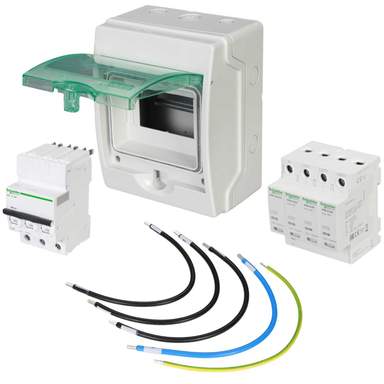
That looks like the sort of prepared cable length on the photo of that kit here:

If that is not possible for any reason, say both sides of the board have other stuff, etc, then you would be looking at top or bottom mounting and a longer run. Another point for the effect of cable length is the "loop area" of the cables, as that has an impact on the inductance. So keep the bunch of SPD cables tight together along the run (and not bound with any other circuit's cables). They don't normally carry current so you don't have any thermal issues doing that.

If mounting at the far end of the busbar don't bother running the cables down to the supply end as what you gain by the tap point being closer to the supply you lose by the extra length of the cables to get there. So if you have to top-mount and the board has the usual bottom feed/switch then I would take the SPD off the top of the busbars instead.

Some TPN boards have enough space inside as they allow for check meter kits, etc, so you might be able to mount the kit inside even if they supply an outside box. You would have to make sure there is enough depth for it, and it has the down side that inspection of the SPD status requires the board to be opened (and normally powered down for safety, of course). Removing SPD for IR testing normally means power off and board open anyway, so that is not such an issue.

Many of the better SPD modules are available with auxiliary contacts that allow an external indicator to be used to monitor them if inaccessible, or to generate some sort of maintenance alarm. Unless you have a high incidence of surges, or a very high value system, that sort of warning light/alarm is probably a bit OTT.
 
Last edited:

Reply to SPD Installation in the UK Electrical Forum area at ElectriciansForums.net

Similar Threads

Has anyone fitted an SPD to a schneider standalone AFDD DB. Isobar P B Standalone Active distribution board, Acti9, 24 AFDD ways This board only...
Replies
4
Views
809
Hi all, Grateful for your expertise regarding my confusion on the below. Context: French rural domestic property Single phase supply, TT...
Replies
12
Views
2K
Someone commented fairly recently that all pics of BG boards posted up are usually RAF and generally turn up in the 'Dodgy trade pics' thread...
Replies
35
Views
3K
So I am a fully qualified spark with my own company, however I also have a few properties I rent out. One of my tenants asked if they can have an...
Replies
84
Views
10K
Hi Guys I've fitted a few emergency lighting circuits to both domestic and commercial installs before, I've come across one I can't get my head...
Replies
19
Views
1K

OFFICIAL SPONSORS

Electrical Goods - Electrical Tools - Brand Names Electrician Courses Green Electrical Goods PCB Way Electrical Goods - Electrical Tools - Brand Names Pushfit Wire Connectors Electric Underfloor Heating Electrician Courses
These Official Forum Sponsors May Provide Discounts to Regular Forum Members - If you would like to sponsor us then CLICK HERE and post a thread with who you are, and we'll send you some stats etc

Electrical Forum

Welcome to the Electrical Forum at ElectriciansForums.net. The friendliest electrical forum online. General electrical questions and answers can be found in the electrical forum.
This website was designed, optimised and is hosted by Untold Media. Operating under the name Untold Media since 2001.
Back
Top
AdBlock Detected

We get it, advertisements are annoying!

Sure, ad-blocking software does a great job at blocking ads, but it also blocks useful features of our website. For the best site experience please disable your AdBlocker.

I've Disabled AdBlock