M

montyfert

hi im trying to fit a smart relay thing on my stairs light there is i switch at the top and bottom.
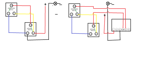
smart relay has 6 connections for no neutral switch
have it working on bench as follows.
L live
L1
L1 from bulb
COM to switch com
S1 to downstairs com
S1
works great on bench .
when i try on my stair light it wont work?

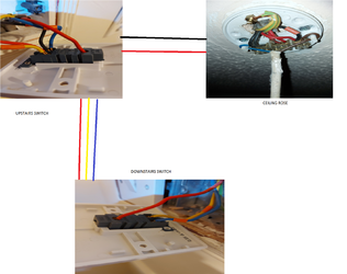
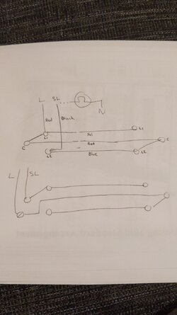
main swith upstairs has
com red
L1 black and blue wires
L2 red and yellow wires

downstairs switch
com red
L1 blue
L2 yellow

ceiling rose
2 block - brown black red wire
3 block - red red wires
3 block - black black blue wires


any advice would ge great berfor i pull all my hair out.
thanks martin
 

Attachments

  • MY WIRES.png
    MY WIRES.png
    1.1 MB · Views: 110
  • WIRING.png
    WIRING.png
    39.5 KB · Views: 82
I thought the s1 terminals were low voltage for the switch but it seems these are all different. Do you have a picture or any info of the module? I've seen one on Amazon that lines up with your wiring and terminal labels. Have you tried a incandescent lamp? It needs to leak some current to work. They are sometimes provided with a capacitor for that purpose.
 
Last edited:
hi yes tried an incandescent bulb didnt make any difference
thing is
when i wired it up on bench like this it works fine.
works fine.png
 
Looking at that it'll work with 2 2-ways as per your sketch

but you'd have to reconfigure the existing house wiring

Have u reconfigured the switch wiring as per your drawing there ?
 
What's not working then? It it powering up and discoverable on the ZigBee hub? Can you switch the lamp on through the hub? The switch is between the red and black on the two core from the upstairs switch, do you have the means to check continuity? To make it look like your diagram you have joined the two reds in the switch which connects the common from the downstairs switch to the module and the black is connected to the common of the upstairs switch to the module. It would be easier not to mess with the switches and just remove the live and switched live from the rose. I've attached two sketches showing the two switching arrangements hopefully they are clear enough. How are you physically mounting this? There are a fair few wires to relocate.
 

Attachments

  • 16373600379548388815080209664494.jpg
    16373600379548388815080209664494.jpg
    223.4 KB · Views: 58
I noticed cef are selling these or similar as
Scolmore ClickSmart+ 100W 1 Gang Smart Switching Receiver, even less documentation though.
 
Are these incandescent only or led ?

Edit I see they're led
 
Last edited:
The simplest way to install this would be in the upstairs switch with a spacer behind the switch( if needed). I would disconnect the 2 core t&e and connect the red in L and the black in L1. That would power your module and allow you to control the lamp remotely. I'd take two cores preferably flex and connect them between the L1 and L2 of the switch where you just removed the 2 core. Connect those to your com and S1.
 

Similar threads

OFFICIAL SPONSORS

Electrical Goods - Electrical Tools - Brand Names Electrician Courses Green Electrical Goods PCB Way Electric Underfloor Heating Electrician Courses Heating 2 Go Electrician Workwear Supplier
These Official Forum Sponsors May Provide Discounts to Regular Forum Members - If you would like to sponsor us then CLICK HERE and post a thread with who you are, and we'll send you some stats etc

Advert

Daily, weekly or monthly email

Thread Information

Title
pulling my hair out trying to fit smart relay.
Prefix
N/A
Forum
UK Electrical Forum
Start date
Last reply date
Replies
10

Advert

Thread statistics

Created
montyfert,
Last reply from
montyfert,
Replies
10
Views
2,718

Advert