I've had a few conflicting opinions on filling parts of the EIC for certain installation types (mainly non-domestic submains), I'm sure many of you can set me straight though ") I have a couple of queries,
I have a couple of queries,
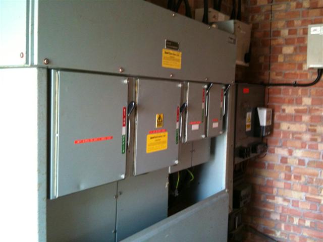
I have a couple of queries,- Maximum demand - This is for the whole board, where you've just added a circuit to a submain with 15 other breakers in it how would you calculate a figure for this box? The same as usual as per the OSG or different with commercial installations? Clamp meter?
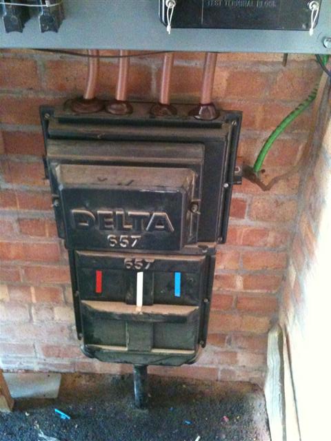
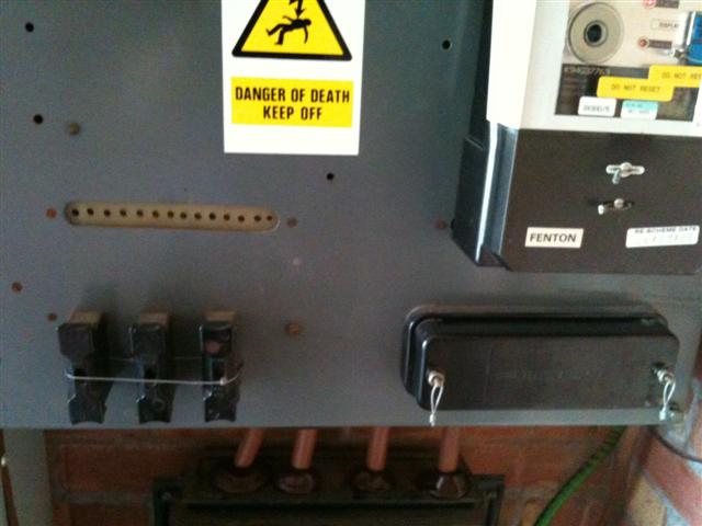
- Main bonding conductor - Where you are working on a submain that is nowhere near any extraneous conductive parts, and all services are bonded from another board, and the MET for the submain is the earth bar inside it, would you put NA in these parts on the cert or would you go round with a wander lead checking continuity on rads etc?
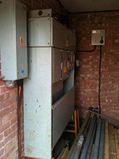
- One the schedule of test results you have to fill in the Ze again. If the circuit you're working on is fed from a single phase submain, which is fed from a 3 phase submain, which is fed from a main 3 phase dis board at the origin of supply, at which point would you measure your Ze? For Zs=Ze+R1+R2 to be true you would have to measure Ze at the submain you're working on (so everything external from the origin of your circuit). The Ze measurement on the first page of the EIC is under the heading "Supply Characteristics" so this means from the closest point to the meter. Does this mean that you could have 2 different figures for Ze, one on the front page from the origin of supply and one on the schedule of tests from the origin of the circuit being worked on?
Last edited: