JS118m

DIY
Mar 25, 2020
24
1
33
Midlands
If you're a qualified, trainee, or retired electrician - Which country is it that your work will be / is / was aimed at?
United Kingdom
What type of forum member are you?
DIY or Homeowner (Perhaps seeking pro advice, or an electrician)
So that I can understand how the electrical energy that I consume is being used I want to fit one of these to my consumer unit (CU) - https://www.amazon.co.uk/EMPORIA-EN...37ML2R/ref=psdc_1938287031_t1_B00G5DZK8I?th=1 The power meter appears to be primarily produced for the USA market and its standards.

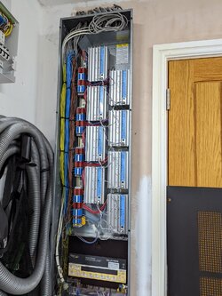
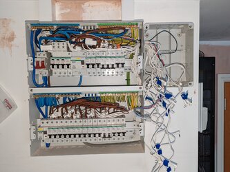
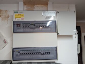
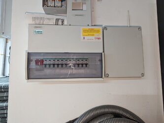
The CU is a Crabtree Starbreaker image attached/here - PXL_20211105_203526416.jpg - https://1drv.ms/u/s!AkQ39xZI1R4EkuBZw6HDW1Rud6QLbg?e=WMsdcU

The device is designed to be installed inside the consumer unit but there may be insufficient space for this so I have two sets of questions one for internal and external fitment. Other considerations i) the installation will be isolated prior to any work inside the CU using the isolator in the meter box, ii) my understanding is that this work isn’t notifiable as there are no new circuits and it doesn’t involve ‘Any addition or alteration to existing circuits in a special location’.

Internal Fitment

Is it acceptable to install such a device in the CU?

The wifi aerial may need to be fitted external to the CU, options i) mounted in a hole drilled in the CU case or ii) externally mounted to the adjacent wall with the aerial cable exiting the case via a hole/gland – are these options acceptable?

External Fitment

In this situation I would propose to bring the CT clamp leads out of the CU and mount the control box adjacent to the CU. In this situation is it necessary/appropriate to mount the control box in an enclosure? Part of the reason for this question is that the manufacturer supplied power lead appears to be single insulated which wouldn’t be acceptable without additional protection (conduit/enclosure etc).

The CT clamp lead/control box connections are 90 degrees which may make it tricky to pass 16 of them through a gland or conduit. For the gland situation I’d thought of cutting a slot lengthways to allow the cable to pass into the gland opening, is this acceptable are there any alternative options?

Power Supply

The power can be taken from an existing breaker for internal or external fitment – is this acceptable?

Fitting another breaker to provide a dedicated supply is another option but this method would I believe make this part of the work notifiable – is my understanding correct?

Many thanks
PXL_20211105_203526416.jpg
 
Last edited by a moderator:
As an Amazon Associate we earn from qualifying purchases.
Cables within an enclosure with mains voltage should be rated to at least that voltage to be compliant with BS 7671. A doorbell transformer for example would either need to have cabling rated to above 230V or the transformer mounted remotely. Zappi car chargers can use a current transformer mounted over the double insulated tails. Those CT's don't look like they are rated to 230V so I don't think this system should be installed.

You are right that the cabling must be double insulated, You would need to mount the whole unit in an enclosure to protect the wires. YT3 trunking could be used to route the cables from the CTs.
 
  • Like
Reactions: JS118m
Cables within an enclosure with mains voltage should be rated to at least that voltage to be compliant with BS 7671. A doorbell transformer for example would either need to have cabling rated to above 230V or the transformer mounted remotely. Zappi car chargers can use a current transformer mounted over the double insulated tails. Those CT's don't look like they are rated to 230V so I don't think this system should be installed.

You are right that the cabling must be double insulated, You would need to mount the whole unit in an enclosure to protect the wires. YT3 trunking could be used to route the cables from the CTs.
Many thanks. I've messaged the company to determine the spec of the cables. Re the YT3 trunking are you saying that it could be possible to create a solution that uses the CT clamps even if they aren't compliant as supplied? Is there a sleeving product that could be used over the CT clamp cable that would make a compliant installation? A flexible sleeve would be easier to install than trunking..
 
I don't think it would be possible to add anything to the cables that would make it compliant and with the main unit not being made to a British standard its not going to ever comply fully. Do you need to monitor each circuit? A second electricity meter could be added if you don't trust the suppliers unit. They are commonly referred to as check meters.
 
  • Like
Reactions: JS118m
I don't think it would be possible to add anything to the cables that would make it compliant and with the main unit not being made to a British standard its not going to ever comply fully. Do you need to monitor each circuit? A second electricity meter could be added if you don't trust the suppliers unit. They are commonly referred to as check meters.
Thanks again. There are two of us living in a 4000' sq ft dwelling, we use circa 7500 Kwh/year with LED lighting etc and I'm keen to know where its going so that we can reduce consumption hence the interest in the circuit level monitoring of the Emporia product.

Sorry to labour the point but if I install the control unit in a separate enclosure and the only components in the CU are the CT clamps with the addition of a sheath around their cable could this be compliant?

I’ve raised the point that you made about the cable spec with the supplier and await a response, they sell in many countries outside the USA so hopefully their cable will be okay. Your post has been very helpful.

 
To be honest, I would generally just look for a CE mark unless I was looking for a device where I knew of a particular standard, I'm not familiar with the requirements of 62368-1. I don't think it would be likely to cause a real issue if you don't comply with the guidance on the proximity of electrical services. Most would code this a C3 on an EICR which would still be an acceptable report. Technically trunking, conduit or partition to separate the wires from the 230V wires are listed as method or compliance.

If I was doing this for my own property I would use something like 170-01012 TWIST-IN 08-PET-BK | HellermannTyton Braided PET Black Cable Sleeve, 8mm Diameter, 5m Length | RS Components - https://uk.rs-online.com/web/p/cable-sleeves/8026110 within the consumer unit to stop everything flapping about and to give some mechanical protection. Regarding the power, I would feed a fused spur from a socket circuit and change the fuse to 3A.

Have you hit the RCD test button recently? there looks like there is a lot of circuits on one.
 
  • Like
Reactions: JS118m
There are an astonishing number of circuits there for a UK domestic property! A guess is 9 RFCs and numerous others.

Personally I would look at putting it outside, and have it powered via a 13A plug or FCU with no more than a 3A fuse. Faults inside a CU are very bad news indeed!

You use is high but not really if you are using electric heating.
 
  • Like
Reactions: JS118m and DPG
There are an astonishing number of circuits there for a UK domestic property! A guess is 9 RFCs and numerous others.

Personally I would look at putting it outside, and have it powered via a 13A plug or FCU with no more than a 3A fuse. Faults inside a CU are very bad news indeed!

You use is high but not really if you are using electric heating.
Thank you for the reponse. Re the use our space heating and DHW is by gas/solar hence the desire to understand where all the eletricity is being used, if it was water I'd think there was a leak in a pipe!

For the power would it be acceptable to set up an FCU next to the CU and take a live feed from the same breaker that supplies the garage sockets? There are spare ways in the board so another option would be to fit a breaker specifically for the power meter, this approach I belive would bring the work within the scope of Part P by adding a new circuit.

There is a second CU (see image) which supplies the lighting control system this is on a different wall to the main CU. I intend to install a second power meter which will also need a power supply, is it possible to put an FCU next to this CU and take a live connection from one of the RCBOs? These RCBOs all supply lighting circuits.

THANKS
 

Attachments

  • PXL_20211105_203655704.jpg
    PXL_20211105_203655704.jpg
    438.4 KB · Views: 128
Is all this fed from a single phase 'standard' 15kVA supply? If so, is the DNO fuse 80A or 100A?
If 100A, there's a real chance of those 80A RCDs being overloaded.
 
  • Like
Reactions: JS118m
Is all this fed from a single phase 'standard' 15kVA supply? If so, is the DNO fuse 80A or 100A?
If 100A, there's a real chance of those 80A RCDs being overloaded.
Thanks - I believe it's a 'standard' supply, I'm back home tomorrow and will have a look and let you know.
 
Thank you for the reponse. Re the use our space heating and DHW is by gas/solar hence the desire to understand where all the eletricity is being used, if it was water I'd think there was a leak in a pipe!

For the power would it be acceptable to set up an FCU next to the CU and take a live feed from the same breaker that supplies the garage sockets? There are spare ways in the board so another option would be to fit a breaker specifically for the power meter, this approach I belive would bring the work within the scope of Part P by adding a new circuit.

There is a second CU (see image) which supplies the lighting control system this is on a different wall to the main CU. I intend to install a second power meter which will also need a power supply, is it possible to put an FCU next to this CU and take a live connection from one of the RCBOs? These RCBOs all supply lighting circuits.

THANKS

Yes, an additional socket can be added to a ring final circuit or a radial circuit from the MCB.
 
  • Like
Reactions: JS118m
Thanks - I believe it's a 'standard' supply, I'm back home tomorrow and will have a look and let you know.
Thanks for alerting me to a potential problem, the main fuse is 80A so I guess all is fine.
 
That raises the question as to why you have 596 amps worth of MCBs on the main fusebox, plus another 94 amps worth on the lighting box!
 
  • Like
Reactions: DPG and JS118m
That raises the question as to why you have 596 amps worth of MCBs on the main fusebox, plus another 94 amps worth on the lighting box!
I guess that's a conversation with the NAPIT approved contractor who designed and installed it 10 years ago. There are several single item breakers e.g. HRVS, alarm system etc which will make understanding consumption easier. A safe installation though?
 
It all looks very neat and tidy, and I've no reason to think it's unsafe in any way, but there does seem to be an awful lot of circuits!
I've always specialised in houses of at least 150m2 upwards and have wired several of around the 400m2 of yours, but I've never fitted anywhere near the number of circuits you have. My 'go to' consumer unit for many years was a MEM 20 module dual rail board, fitted with a main switch and two RCDs, occupying 6 modules, leaving room for up to 14 MCBs.
 
  • Like
Reactions: JS118m
It all looks very neat and tidy, and I've no reason to think it's unsafe in any way, but there does seem to be an awful lot of circuits!
I've always specialised in houses of at least 150m2 upwards and have wired several of around the 400m2 of yours, but I've never fitted anywhere near the number of circuits you have. My 'go to' consumer unit for many years was a MEM 20 module dual rail board, fitted with a main switch and two RCDs, occupying 6 modules, leaving room for up to 14 MCBs.
This is the final part of the installation - the Lutron Homeworks. Having lived with it for 10 years we're every pleased. Just need to workout how to reduce the circa 7500Kwh/yr electricity consumption, I'm looking forward to getting the Emporia system up and running.
 

Attachments

  • PXL_20211105_204001350.jpg
    PXL_20211105_204001350.jpg
    598.4 KB · Views: 114
Central vacuum system installed as well? Very nice.
 
  • Like
Reactions: Jim_e_Jib
Central vacuum system installed as well? Very nice.
Thanks to everyone who assisted by replying to my question. The job is now complete and the energy monitoring proving informative. The Emporia instructions illustrate fitting the CT claps and the monitor inside the CU but for UK installtions I don't think this is really feasible so I used two enclosures which made the job alot easier.
 

Attachments

  • PXL_20211112_142218127.jpg
    PXL_20211112_142218127.jpg
    556.5 KB · Views: 91
  • PXL_20211126_175045770.jpg
    PXL_20211126_175045770.jpg
    264.8 KB · Views: 93
  • PXL_20211126_175106809.jpg
    PXL_20211126_175106809.jpg
    302 KB · Views: 85
There looks to be a lot of MCBs/circuits fed from single RCDs there.
 
  • Like
Reactions: nicebutdim
Crikey, lots of stuff going on in those CUs!
Looking at the pic of the second CU, in post #10, directly above the 3rd and 4th breaker there seems to be a bit of exposed copper hanging about?
 
  • Like
Reactions: JS118m
Crikey, lots of stuff going on in those CUs!
Looking at the pic of the second CU, in post #10, directly above the 3rd and 4th breaker there seems to be a bit of exposed copper hanging about?
Thanks for taking the time to mention this it's a small shaving off the outer insulation.
 
I recently signed up to the looped energy app. It's currently free and just gives you the energy readings from the smart meter every 30mins.
 

Similar threads

OFFICIAL SPONSORS

Electrical Goods - Electrical Tools - Brand Names Electrician Courses Green Electrical Goods PCB Way Electric Underfloor Heating Electrician Courses Heating 2 Go Electrician Workwear Supplier
These Official Forum Sponsors May Provide Discounts to Regular Forum Members - If you would like to sponsor us then CLICK HERE and post a thread with who you are, and we'll send you some stats etc

Advert

Daily, weekly or monthly email

Thread starter

Joined
Location
Midlands
If you're a qualified, trainee, or retired electrician - Which country is it that your work will be / is / was aimed at?
United Kingdom
What type of forum member are you?
DIY or Homeowner (Perhaps seeking pro advice, or an electrician)

Thread Information

Title
Fitting a Power Meter to a CU Part 1
Prefix
N/A
Forum
UK Electrical Forum
Start date
Last reply date
Replies
24

Advert

Thread statistics

Created
JS118m,
Last reply from
Aaron b,
Replies
24
Views
7,457

Advert