• IMPORTANT: Please note that nobody on this forum should be seeking from or providing advice to those who are not competent and / or trained and qualified in their field (local laws permitting). There is a discussion thread on this global industry-wide matter HERE. This also has more information about the warning with regards to sharing electrical advice in some countries. By using this forum you do so in agreement to this.

Discuss Parallel earth paths and design in the Electrical Forum area at ElectriciansForums.net

Welcome to ElectriciansForums.net - The American Electrical Advice Forum
Head straight to the main forums to chat by click here:   American Electrical Advice Forum

Reaction score
37
Christmas crew, hope you all enjoying yourselfs. Ive been reading a thread on another forum about parallel paths. In certain installations, namely industrial/ some commercial, where the use of metal conduit, SWA, and steel framed building prevails. In such installs there is really is no way to avoid parallel paths, not that theyre a bad thing as it helps lower ZS, help lower touch voltages, and helps keep extraneous stuff at similar potential. This got me thinking about design of such circuits in these environments ! Can the design of a circuit, say for example an SWA ring final with its steel wire used as CPC, with metal boxes fixed to the metal beams of building structure (which be bonded and also connected to earth at multiple points by other metal clad circuits), be designed with these parallel paths as a factor ? Or does each and every circuit need to be designed within its limitations based on OCPD, conductor size, and ZS, based on the notion that there are no parallel paths present ? Can these parallel paths through a building structure even be measured ? Food for thought really as my small works is miles away from anything like the above, but with all things its worth knowing about to satisfy my inner chakkra. Similar to that Tesla guy, im thinking, if everything is earthed aound us then why have wires and cables, the earth is a parallel path ! Yeah 😀
 
According to regulation 543.2.6, certain extraneous parts can be used as a protective conductor. I'd suggest that the cpc is sized on one path rather than trying to calculate the sum of the parallel paths as each would have a different impedance, particularly for different materials at different temperatures.
 
According to regulation 543.2.6, certain extraneous parts can be used as a protective conductor. I'd suggest that the cpc is sized on one path rather than trying to calculate the sum of the parallel paths as each would have a different impedance, particularly for different materials at different temperatures.
Useful to know as you mention.
 
There’s a video by LA Sparks where the Zs ends up a fraction too high on a garden circuit and from memory he solves it by adding some steel trunking to the CPC path.
 
I'd suggest that the cpc is sized on one path rather than trying to calculate the sum of the parallel paths as each would have a different impedance,
Wise guidance. Modern day electrical installers tend to ensure that the circuit supply cpc is effectively independent. Parallel paths are best viewed as a bonus rather than a "partner" in ensuring effective operation of the OCPD
 
100% with @LastManOnline here, I would always want the primary CPC to be adequate and under my control as designer (or installer).

Things like SWA armour have a known CSA and are unlikely to have faults outside of the termination glands which would usually be easy to inspect, conduit more joints but designed as CPC capable and joints as large as tube (excluding that horrible grub-screw system).

Metal trunking I'm less sure of, could be OK but often only a few small contact points for fault current to flow so a concern if very big PFC, and a bit more risk of it being unscrewed for maintenance or due to vibration somewhere.
 
Wise guidance. Modern day electrical installers tend to ensure that the circuit supply cpc is effectively independent. Parallel paths are best viewed as a bonus rather than a "partner" in ensuring effective operation of the OCPD

Wise guidance. Modern day electrical installers tend to ensure that the circuit supply cpc is effectively independent. Parallel paths are best viewed as a bonus rather than a "partner" in ensuring effective operation of the OCPD
I agree that an independent cable cpc is easier all round for sure, maybe a waste of cable in some instances, but maybe more safer and idiot-proof as a result. My point for posting was to consider a large scale building with each circuit using the metalwork of the structure for CPC connection, and would that be an option ? The reason being to save money on cabling.
You see, call me an optimist, but I can imagine in the far future that alot of devices and equipment will be super low voltage where connection to earth would be without cables atall, just place it anywhere where the structure is earthed. I know its a bit sci-fi but its imaginable !
 
I agree that an independent cable cpc is easier all round for sure, maybe a waste of cable in some instances, but maybe more safer and idiot-proof as a result.
If you have multiple circuits going to roughly the same place, you can get away with a CPC for the lowest Zs case.
 
Ah, never tried that to link final circuits, never thought that was a recognised option tbf. For sub mains s then yeah thats exactly what that is!
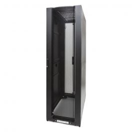
In one case I had 6 final circuits going to a set of 6 x 19" racks, so just had two CPCs, each of the same 4mm size as needed for the CPC. The racks were all bolted together and the CPCs from a common block (so 2 CPC to block, 6 from there to each 5kVA UPS).
 
In one case I had 6 final circuits going to a set of 6 x 19" racks, so just had two CPCs, each of the same 4mm size as needed for the CPC. The racks were all bolted together and the CPCs from a common block (so 2 CPC to block, 6 from there to each 5kVA UPS).
Yea thats all good, never touched that sort of cabinetry !
 
I agree that an independent cable cpc is easier all round for sure, maybe a waste of cable in some instances, but maybe more safer and idiot-proof as a result. My point for posting was to consider a large scale building with each circuit using the metalwork of the structure for CPC connection, and would that be an option ? The reason being to save money on cabling.
You see, call me an optimist, but I can imagine in the far future that alot of devices and equipment will be super low voltage where connection to earth would be without cables atall, just place it anywhere where the structure is earthed. I know its a bit sci-fi but its imaginable !

But at such low voltages you probably wouldn't need an earth connection.
 
The thing with distributing ELV power is the much higher impact of voltage drop, not to mention the higher relative level of any induced noise. So I suspect we will still be sending 230V around the building but maybe have more multiple USB-like outlets for stuff that just needs a few W at 5V or similar.
 
Yeah it's amazing really. More brighter people than me must have thought about it all; who would have thought 20 years ago that a phone could be charged for example without even plugging it in !
 
I have just fitted some tray work supported from the purlins above and threaded stud. To the tray I have bolted 5x 10 way klik boxes, which have a metal slot in them for easy attachment which must be earthed. I am now struggling to get an r2 reading (0.01-0.02ohms) !
My question is, should I remove cpcs from klikboxes, wago them together and re-test? Or just leave as it is and document original reading?
Is the low path back to the MET coming via the bonding of the tray and then through the tray itself?
Would removing tray bonding during continuity testing help?
 

Reply to Parallel earth paths and design in the Electrical Forum area at ElectriciansForums.net

Electrical Forum

Welcome to the Electrical Forum at ElectriciansForums.net. The friendliest electrical forum online. General electrical questions and answers can be found in the electrical forum.
This website was designed, optimised and is hosted by Untold Media. Operating under the name Untold Media since 2001.
Back
Top