Discuss 32amp Single phase rackmount distro in the The Welcome Forum area at ElectriciansForums.net

Reaction score
0
Hi,

Just someone setting up a mobile soundsystem for small pubs/clubs with a few questions about a distro. People IRL can't seem to answer my questions and the pro-sound light forums generally get too much conflicting information.


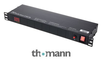
I am about to build something like above. Except I am not paying £400+ for £100 worth of junk parts.

I have about half the stuff ready, case sockets, ammeters, I have a industrial changeover switch I intend to use so I can select between 16a, off and 32a on the input. I also want to know if Wylex mini RCBO type C are good RCBOs. I know some of the cheaper ones get grief, I also know that spending £50 per RCBO on Schneider might be overkill.

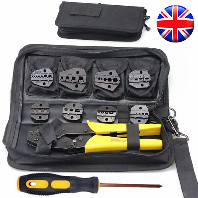
My questions pretty much come down to 6mm 4mm 2.5mm wiring, crimping/soldering for neutrik 20a powercons (and I know the answer is crimping but not sure if I should be using 4mm or 2.5mm wire) and terminal blocks/din placement. I also want to get a circuit tester built into the box but not sure where to get the parts, I'm sure there must be a kit for this now.

I know this is the welcome forum, so hopefully someone could direct me to the best forum diy/commercial for this. Hoping I can just share the project build and absorb any knowledge or advice like a big sponge.
 
1. a changeover switch for 16 or 32A input is overkill.
simply have a 32A input and different supply cables for 13, 16 and 32A

2. when you say you want a circuit tester built in, what are you wanting to test?

Your problem with a project like this is mainly a paperwork issue.
Because you are not using a type tested or CE marked appliance, you are responsible for the design and testing/certification of the device.
if it was a project for home use, it may not be quite such a big problem however, when using it as part of a commercial enterprise the law is much firmer in that you have a duty to ensure that the equipment is safe.

I would not recommend trying to build this if you intend to use it for public entertainment or hire.

@Rockingit is heavily involved in the entertainment and mobile events field and may have some more helpful advice.
 
1. The scenario I am preparing for is the eventual situation where I end up going to a venue that does not have RCBO installed on their 16amp socket as per 2018 regulations. I can't just plug an off the shelf 32amp distro into it, I could end up drawing 32amp from their unprotected 16a socket. In this situation it would be acceptable for the venue to do a risk assessment and know they are protected by my equipment.

I could very well plug the off the shelf 32a unit with a 13a or 16a jumper and if no protection down the line I'm pulling 32amp through 16a or 13a socket even if just briefly.

The changeover switch and additional 16amp RCBO on the input is entirely a safety feature for my own peace of mind, exactly the same with the ammeters etc... My goal is having 1 piece of equipment that comfortably covers 16a and 32a single phase supply...

2. 3 light circuit tester on input. I know I could just plug one into the socket directly or into one of my other sockets but it would be nice to built one into the unit.

The reason I am building this unit is that there are no off the shelf devices which offer the outputs and safety solution I require. I would need the unit I linked too above, and a 16amp version of the unit and it would still not have RCBOs. That's £800 with no RCBOs and low quality components.

The unit spec:
The unit input will be 32a ceeform input with an 100a ammeter.
It would be nice to have a 3 light circuit tester built into the panel.
This will then reach a switch which will allow me to direct current to either 'off' '16a RCBO' or 32a RCBO' into the terminal distro. Then the outputs will be 8x20a powercon outs and 1x16amp socket with it's own ammeter design to supply small stage power or 'gear' belonging to DJ's musicians lighting engineers why.

I am pretty sure this is the route I am going, and I am not disregarding advice to use 'off the shelf' solutions, it wouldn't be dry hired, as a matter of fact I wouldn't let anyone apart from myself handle it. I am actively looking for criticism so whatever I end up with is an overbuilt safe solution. And it's a small project that years later I can build on.
 
Last edited:
Thanks @James

So, to the OP, rearrange the question: What is it that you need to power?

From my own (reasonably extensive) experience, your average U.K. pub is good for a double 13A socket and if you’re lucky in a club you might find a 16A socket, very occasionally 32A. However, your kit remains the same. At a guess you’ve got a few bits of backline, maybe a PA with class 4 amplifiers (probably built in) and if a band is really flash maybe a dozen led parcans (or similar). All of which will run on a single 13A (yeah…… they really will) unless there’s something peculiar going on. Also - Powercon/Tru1 outlets may look good, but what’s the point when the bands gear is all on 13A straight out of practicing in a garage? A current meter might look flash but what does it actually help? (Besides…. any band in a pub is looking at a) the MD and b) the next shag, not a dial).

I’ll level with you here - there’s absolutely no difference at this level between a rack mount device like this and a bunch of 4 ways. In fact, a bunch of 4 ways actually benefits you by adding flexibility to distributing the load over whatever power you find available. A decent 4 way will set you back £15 and a 16>13 adaptor about £5. You can donate £100 to cancer research for the advice and still be up on the deal ☺️.

Alternatively, if you REALLY want to invest in a rack mount device look at Thomann or Gear4Music instead!
 
 
All things considered I agree that some of the commercial PDU offerings are either too shoddy, too expensive or both. When we designed racks, we used to design our own PDUs too. But that was in quantity, for large contracts. I wouldn't bother making a one-off for myself these days, like @Rockingit I would usually bypass the issue with a K9 and some 4-ways. I've strung a lot of K9s and Toblerones together over the years. Anyway, if you opt for making something, some points in random order:

I don't like original blue / grey 20A powercon NAC3... series for general distro. Not least because they are not designed to be plugged and unplugged live (and if you've seen one flash over, you'll know why.) If you must use a locking compact connector, I would consider the Powercon 16A True1TOP series over the older 20A.

Not sure you mentioned this but obviously the 16A socket and the Powercons need overcurrent protection at 16A when the selected source is 32A.

I tend to ignore 3-lamp supply status indicators built into gear. The important one is 'earth present' but this can very easily give a misleading indication. It only takes a very weak, high-resistance earth connection to make the light glow merrily, but when the chips are down and you have a fault, it turns out that the 'earth connection' was only a bit of backline gear resting against a radiator and the supply earth is not fit for purpose. A stand-alone tester in a plug is a little better in that it won't give a false indication due to parallel earth paths, but if you really want to know whether the supply is safe, there's no substitute for a Zs test with a real tester.

Unless you intend to bunch umpteen circuits together all fully loaded, 2.5mm² tri-rated is fine for 16A / 20A. Did you know you can get Powercons with screw terminals? If you are relying on insulated blue 0.25" push-on connectors at that current, make sure they are good branded ones used with a matching die set in the tool. Cheap push-ons get flaky at 16A.

Because your distro might get connected by a short length of cable to a socket electrically close to the venue installation's origin, allow for relatively high PSCC and PEFC. You'll want to be sure that chunks of burning ammeter don't come flying out of the front panel in the event of a 5kA fault.

Test the feck out of it on completion. Flash test, ducter earth continuity etc. As it's not being made to a BS as an assembly, you need to be sure it offers no lesser degree of safety. Only using it yourself doesn't limit your responsibilities under EAW... it's got to be as safe for you to use as anyone else.
 
I don't like original blue / grey 20A powercon NAC3... series for general distro. Not least because they are not designed to be plugged and unplugged live (and if you've seen one flash over, you'll know why.) If you must use a locking compact connector, I would consider the Powercon 16A True1TOP series over the older 20A.

I agree on powercon not being good as a general distribution connector, it does make a good latching alternative to an IEC on appliances though.

I'm not too keen on the true1 though, I've seen a fair few failures now. The most common issue I've seen is the softer plastic wearing out and allowing the contacts to go a bit wonky, or allowing the plug to turn too far in the socket and making contact between the wrong parts.
 
Is that with the original yellow latch ones or the TOP series with metal latches? I know Neutrik discontinued the original type because of similar problems of them not being robust against incorrect engagement and rotation. We don't give them a particularly hard life in most of our applications, but as a precaution I've been purging the originals and AFAIK we only have the TOPs now.

Before the True1 came out, I wanted a power connector for my video systems that would fit into a standard 24mm panel cutout but specifically avoided using NAC3A blue Powercons not only because of the non-breaking rating and originally the self-unscrewing cover, but because of the very limited protection against shorting to the shell of a BNC panel jack. Basically the back panel of the units I built would have a dozen XLRs, a dozen Ethercons, and a few dozen BNCs. Amongst all those BNCs would be the one mains inlet and I could envisage someone groping down behing the unit in the dark on a cramped stage, and managing to engage a live blue end onto a BNC. It's not as blatant as the figure-8 power lead onto pins 1 & 2 of an XLR3 but it's pretty close. Anyway, the True1 solved this for me and I've used them ever since.
 
Appreciate the responses. I will be using this distro to power a crest 8001 and other heavyweight crests and probably have a 10k matrix plugged into it at 8ohms so would only draw 1/2 power when I get around to building some bigger subs in the summer, but that system would need something bigger eventually. I think all the crests all have MCB power switches although only one output on the distro at a time might even approach full load, so I don't need MCBs on 20amp powercons. That said I'm not sure yet. I just want everything here before I start cutting up the box. Would I want a 20amp mcb on each of the powercon outs? It's just occurring to me now I might plug a 10k matrix with a 32amp plug and jumper into it at some point although it wouldn't be connected to a load big enough to use it past half power.

Regarding the ammeters. I have a 20amp on (for the 16 amp passthrough) and a 100amp ammeter for the input. I put one of these (but the DC one on my car after I installed a stereo) I recognised them on the penn elcom distro immediately and figured why not. I want the ammeters because I plan on being able to draw every watt of safe power I can.

I was looking at just running a DIN rail across the centre of the casing inside with a bracket and some 2-6mm 3x12 way terminal blocks. 6mm from the 32amp in... then 4mm to each white powercon socket and the 16amp ceeform. (I will buy neturiks, the updated old style and not the £1 chinese ones). Then buy the little sleeves to cover them. I might spend some more time looking at a good pair of crimps. I don't intent to spend £200-300 on the neutrik crimps. Was just going to use 4.8mm spade terminals with a cheap pair of ratchet crimps.

Again this is why I'm asking this stuff. Eventually I will probably want to do a 63/120a single or a some sort of 3phase. I work in IT mainly so like once every now and then I have to plug a 120a ceeform into the bottom of a rack. I might edit this post and include some of the things I'm looking at buying and let me know if any of it is junk (bad crimps/fastons/blocks).
 
Don't forget inrush. What MCB curve do you plan to use and why?

Was just going to use 4.8mm spade terminals with a cheap pair of ratchet crimps.
If I were using grey NAC3...B outlets with 4.8mm terminals, my preference would be to solder. I don't like 4.8's very much at all and certainly not at 20A, most are only 'rated' to 15 with a trailing wind. 6.3mm as used on True1's are better although not perfect.

only one output on the distro at a time might even approach full load, so I don't need MCBs on 20amp powercons.
By this logic, seeing as I never deliberately overload any of my house wiring, I don't need a fuse box. I could connect all the circuits directly to the 100A main switch. Are you proposing to leave them protected at 32A when on a 32A supply?
 
I think all the crests all have MCB power switches although only one output on the distro at a time might even approach full load,

None of the outputs will get anywhere near full load with one of those amplifiers plugged into it.

so I don't need MCBs on 20amp powercons.

Yes you do, you can't have a 20A connector directly fed by a 32A supply, you need an OCPD.

Regarding the ammeters. I have a 20amp on (for the 16 amp passthrough) and a 100amp ammeter for the input. I put one of these (but the DC one on my car after I installed a stereo) I recognised them on the penn elcom distro immediately and figured why not. I want the ammeters because I plan on being able to draw every watt of safe power I can.

As Lucien has already said above you need to ensure that these meters will be safe under fault conditions and not explode and start a fire. How are you protecting these meters against faults?
I was looking at just running a DIN rail across the centre of the casing inside with a bracket and some 2-6mm 3x12 way terminal blocks. 6mm from the 32amp in... then 4mm to each white powercon socket and the 16amp ceeform.

You need protective devices in there, you can't just join everything together. Everything will need RCD protection, the Powercon need 20A protection, the 16A outlets need 16A protection.

Again this is why I'm asking this stuff. Eventually I will probably want to do a 63/120a single or a some sort of 3phase. I work in IT mainly so like once every now and then I have to plug a 120a ceeform into the bottom of a rack.

If you're working on big enough gigs that the PA system needs a 63A single phase supply then why on earth are you messing around with making it yourself? If there isn't enough money in a gig if that scale to hire or buy the distro then you're really not charging enough.
 
Don't forget inrush. What MCB curve do you plan to use and why?
Type C RCBO Based on reports that the higher powered Crests (9001) have been known to trip type B on powering on.

If I have to install 8 MCBs for 8 outputs then I'd perhaps put in 4 Type Cs MCBS and 4 Type B. Question then is do I put them all at 20a or maybe put some smaller ones on. 4 x 20amp TYPE Cs and 4 x 16a or 10a Type Bs for smaller amps and processing.

If I were using grey NAC3...B outlets with 4.8mm terminals, my preference would be to solder. I don't like 4.8's very much at all and certainly not at 20A, most are only 'rated' to 15 with a trailing wind. 6.3mm as used on True1's are better although not perfect.
So I've gone from soldering to crimping back to soldering... So right now I usually use this lead free 'silver bearing Rosin core' solder. I have a nice enough chinese 90-110w digital iron. What is the best solder to use for a joint like this... Highest melting point? Once soldered should I tape the joint up, wrapping around the powercon or sleeve each tab then sleeve each individual connection then put on a rubber sleeve in the event the joint breaks it will just be loose in it's rubber sleeve.

By this logic, seeing as I never deliberately overload any of my house wiring, I don't need a fuse box. I could connect all the circuits directly to the 100A main switch. Are you proposing to leave them protected at 32A when on a 32A supply?

No I get you. I wondered this about the Penn Elcom distro posted. Looks like all their 20a outputs are protected by a single 16a mcb, that said I doubt the powercons are neutriks in that device. My reasoning is each of my amps have their own MCB switch built in but that would leave the wiring between the 32a rcbo and the amps own mcb switch on the amp open to 20a+ of current until this 32a tripped. So I need 8 additional MCBs...
 
do I put them all at 20a or maybe put some smaller ones on.
Can't see the point of fusing anything down, not as though it would help limit tripping the overall supply. We have the old chestnut of whether all possible connected flexes including 0.75mm² IEC tails are protected against fault current (not overcurrent) by a C20, if you wanted that possibility rather than going via a 13A block. I can't remember the concensus the last time I asked that one.

What is the best solder to use for a joint like this... Highest melting point?
Ordinary 60/40 leaded solder is the best and I still use it for anything critical that is compatible with it. It's prohibited from general electronic construction usage and you won't find it in any TV made since the ROHS directive, but it is not banned outright (e.g. cars, aeroplanes, medical equipment can still use it) because it's better than lead-free. From a practical perspective, anything made with 60/40 has to be repaired with 60/40 and anything made with lead-free has to be repaired with lead-free. I keep five different grades of solder on the bench but look inside any pieces of equipment I made and the chances are it'll be 60/40. I use Multicore Crystal 511 as a general-purpose no-clean.

sleeve each individual connection
I generally do. For mains connections I heat-shrink, but for ELV I use Hellermann sleeves that can be slid off and back on again.

in the event the joint breaks it will just be loose in it's rubber sleeve.
This should never happen. Put the connector in a vice and yank on the cable and you should be able to rip the contact right out of the connector body. If your soldering is not sufficiently strong and reliable as to guarantee to withstand this, don't solder the connectors.

So I need 8 additional MCBs...
Four pairs of sockets? Maybe a problem with inrush, but then if two loads paired together are going to trip a C20, maybe all of them together will trip a C32. Having been stuck mid-show after a random trip unable to get the main panelboard MCCB back on, makes the money spent on sequenced distros seem positively good value.

OTOH, keeping things in perspective, I've done a show for 5000 people on a shared 16A 3-phase (OK not massive bassy noisy stuff) and a rock act in a sport stadium on 63A single. Some years ago I demonstrated that I could play my workshop sound system loud enough to hear from the other side of the road, on a 315mA fuse, I think I posted about it on here when someone was trying to persuade their customer that a dedicated 32A circuit was not needed for their lounge listening system.
 
Last edited:
I think I'm getting closer to a solution. So on the 8 powercon outs I will have 6 x 20a Type C MCBs and 2 x 10a Type B MCBs, the purpose being 10a to protect the IEC cable on the processing unit for the crossover and a spare that I could use for a laptop charger or additional none amp stuff.

Then the next thing in question is protecting the Ammeters. The ammeter units should be rated for 20a. The 100a one is just a 20a unit with some sort of induction coil that will loop over the 6mm input and doesn't measure the current directly. Now if I use 12way terminal blocks, that is 1 for input, 2 for 16amp socket, 3-10 for powercon leaves me with 11 and 12 terminals spare. Should these be used for the ammeters then I can inline their own protection like a fuse or more small MCBs. Or perhaps I could just use these 2 inputs for 2 extra 3 pin plugs for a laptop charger and wiring the ammeters directly to the plugs after the RCBOs, but then I suppose I couldn't do that with the 100a ammeter because it could only take 20amps and potentially could receive 32amps... Which means I could wire that one in after one of the other MCBs on the powercon outs.
 
Technical arguments aside (and some swerves around the reqs of BS7909 as well) there’s a disconnection between where this post has described it’s start and where it’s at now…. A pub gig is very rarely a toured 2/3 way crossover with processing and 63/1 scenario - so which, exactly, are we providing you advice on?
 
Technical arguments aside (and some swerves around the reqs of BS7909 as well) there’s a disconnection between where this post has described it’s start and where it’s at now…. A pub gig is very rarely a toured 2/3 way crossover with processing and 63/1 scenario - so which, exactly, are we providing you advice on?
Powering a 2-3k 4way system initially, perhaps lights/stage also, then expect to use the same distro for 6-12k over the next year or so although not loaded with any stage or lights.

The help I need is just to make sure I'm getting the right parts like making sure the terminal blocks are OK. Just to be pointed in the right direction if I am doing something wrong. Looking at the original Penn Elcom box I now realise it has 2x16a mcbs so even though it has 20a powercon (even if not neutrik) they will never actually receive 20a which I didn't notice when I started reading the thread.

I wire the 32amp ceeform input with 6mm tri into three of the following blocks, I will place the 3 blocks along a din rail mounted along the middle of the inside of the box. These are the only 32amp blocks I can find that will take 2mm-6mm wire and rated at 32a.


Then from the blocks 4mm tri to the neutrik 20a sockets through MCB. They will be crimped using:


and I will use neutrik faston 4.8mm connectors rather than 4.8mm spades as they may only be rated for 15a and I know the neutriks are 20a. I will then heatsink the faston and use the SCDR sleeves


Each socket will have it's own MCB. I have added a 13amp socket I plan to keep a circuit tester in or for charging phone/laptop/convenience.

Of the 12 terminals:

1. 6mm (32a ceeform in) RCBO 32amp type c (The induction loop from the 100a ammeter will measure current on this wire)
2. 4mm (16a ceeform out) RCBO 16amp type c (20a Ammeter installed inline (relies on 16a rcbo protection)
3. 4mm (20a powercon 1) MCB 20amp type c
4. 4mm (20a powercon 2) MCB 20amp type c
5. 4mm (20a powercon 3) MCB 20amp type c
6. 4mm (20a powercon 4) MCB 20amp type c
7. 4mm (20a powercon 5) MCB 20amp type c
8. 4mm (20a powercon 6) MCB 20amp type c
9. 4mm (20a powercon 7) MCB 10amp type b
10. 4mm (20a powercon 8) MCB 10amp type b
11. 4mm (13a socket) MCB 13amp type b
12. 2.5-4mm (100a ammeter rated up to 20a) protected by MCB 6amp type b

Everything here is pretty much perfect for my needs, the only thing I think might need changing is the 9. and 10. My processor is fused at the back and I have wired a blue neutrik socket into the back of it on a patch panel. Which means it could be patched into a 20a supply although the 10amp sockets are for this, but they are on the distro, not the back of the unit.
 

Reply to 32amp Single phase rackmount distro in the The Welcome Forum area at ElectriciansForums.net

Similar Threads

  • Locked
  • Sticky
Beware a little long. I served an electrical apprenticeship a long time ago, then went back to full time education immediately moving away from...
Replies
55
Views
5K
Please advise what I should test / check next. My usual qualified electrician who did all of the work here is in Ireland for 4 weeks and not...
Replies
45
Views
3K
I wired a new circuit in my garden last year. One thing I wasn't sure of but figured it can't be much of an issue was having two rcds on the same...
Replies
9
Views
2K
I'm a fully qualified electrician but I've always worked for companies. Currently a maintenance electrician at a hospital. I've done domestic in...
Replies
15
Views
3K
Hi, I'm a DIY'er, new to this forum. My situation is, I'm laying a new kitchen ring circuit for my sister. The ring will supply the obvious...
Replies
11
Views
17K

OFFICIAL SPONSORS

Electrical Goods - Electrical Tools - Brand Names Electrician Courses Green Electrical Goods PCB Way Electrical Goods - Electrical Tools - Brand Names Pushfit Wire Connectors Electric Underfloor Heating Electrician Courses
These Official Forum Sponsors May Provide Discounts to Regular Forum Members - If you would like to sponsor us then CLICK HERE and post a thread with who you are, and we'll send you some stats etc

YOUR Unread Posts

This website was designed, optimised and is hosted by Untold Media. Operating under the name Untold Media since 2001.
Back
Top
AdBlock Detected

We get it, advertisements are annoying!

Sure, ad-blocking software does a great job at blocking ads, but it also blocks useful features of our website. For the best site experience please disable your AdBlocker.

I've Disabled AdBlock