W

Worcester

Don't want to get into a discussion here about when to earth the array or not.

Lets' assume it MUST be earthed.

How are people doing it?

1) Attaching an earth strap (braid or cable?) between each panel and the rail (one or both?), then joining all the rails together (parallel), and then a single earth.

2) Joining the rails together in parallel then a single earth (And making the assumption that the panels mounts will earth the panels to the rails)?

Or:
3) Make the assumption that the panels and panel mounts will join all the rails and panels together and attaching a single earth cable to one rail?

4) Any other way

5) What do you think should be Best Practice?

Thx
 
I have only earthed one. I went for your option 3. I used a couple of external grade earth clamps linked together that fitted around one of the main rails.

My reasoning was that the metal/metal joints will provide good enough contact. I am in two minds though because of the aluminium oxidation issue and the disimilar metals issue. I'll go back after one year (its a standard thing I intend to do) to see what it looks like.

I think there is a good argument that goes along the lines of better protection against electric shock would be provided by a big notice saying do not touch the array if you are standing on a metal ladder touching the ground, rather than expecting scores of electrical bonding connections to panels and rails to keep working after n years.

Regards
Bruce
 
Single wire to rail - and use the panels as interconnections since these are firmly clamped in - Its not different to using the socket screws to bond the metel back box on a socket outlet.
 
Thanks for your thoughts, let's keep this going for a while, because we're hovering between 1 and 2 !

Good old Sharp's installtion manual says:

GROUNDING
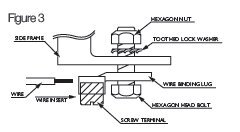
All PV modules must be grounded by electrical connection of the module frames to ground. Please be careful in arranging the system ground so that the removal of one module from the circuit will not interrupt the grounding of any other modules. The modules should be grounded to the same electrical point as described below. Each PV module has a hole on the side frame for either a bolt, nut and washer grounding the module to the frame, a ground lug fastened by bolt or screw, or appropriate screw (hardware not provided). An example of acceptable ground connection using a bolt, nut and washer retaining a ground lug is shown in figure 3. In a connection of this type, the hardware (such as a toothed locked washer / star washer) must score the frame surface to make positive electrical contact with the frame. The ground wire must be considered within the requirement of local regulations at the site of installation.
Image here:
Earthing.jpg

And Schletter do a special clamp that is deisgned to penetrate the surface of the frame slightly (it has a point on the underside).
 
Are we talking about bonding the frame or earthing the panels.

If the frame is floating then by bonding it could lead to a situation where if there is a fault within the equipotential zone and the frame was not ordinarily an extraneous conductive part, then by the act of bonding it could introduce, the prescence of fault currents onto the frame that would otherwise be external to the bonding system

As for earthing the modules aren't they Class II equipment.
 
Last edited by a moderator:
We're talking about
2.2.1 Earthing of exposed conductive parts (array frame)
as per the guide, and the assumption is this must be earthed.
 
Last edited by a moderator:
We're talking about
as per the guide, and the assumption is this must be earthed.

To expound this why is the frame considered an exposed conductive part. The panels are Class II and I believe that DC cables have a double insulation, as the BS 7671-2008 gives the definition of an exposed conductor part as being

"Conductive part of equipment which can be touched and which is not normally live, but which can become live when basic insulation fails"

So would think that there is little reason to earth the frame.
 
@malcolmsandford, as per my opening post, I do not want to get into a discussion as to wether in a particular instance an array should or should not be earthed, I suggest we take THAT discussion into a different thread.

Don't want to get into a discussion here about when to earth the array or not.

Lets' assume it MUST be earthed.

How are people doing it?
 
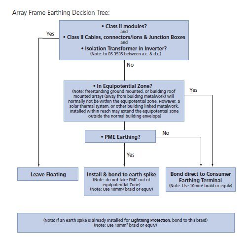
2.2.1 Earthing of exposed conductive parts (array frame)
The majority of installations will utilise class II modules, class II d.c. cables & connectors and be connected to the mains via an inverter with an isolation transformer. This approach is recommended and permits the array frame to be left floating.
Notes to terms used in diagram:
a) Isolating transformer: An isolating transformer is one in which the input and output windings are electrically separated by double or reinforced insulation (see BS 3535).
While the hazards presented by an array frame reaching the system d.c. potential may be significant, the potential fault/shock current is typically much less than that from a mains fault. Hence it is the electrical separation of the mains from the d.c. using an isolating transformer that is the key determining factor when assessing the requirement for array frame earthing.
b) ‘Equipotential Zone’ is defined as a zone in which exposed-conductive parts and extraneous-conductive parts are maintained at substantially the same potential by bonding, such that, under fault conditions, the differences in potential between simultaneously accessible exposed and extraneous-conductive parts will not cause electric shock. ‘Extraneous-conductive parts’ are conductive parts liable to introduce a potential, generally earth potential, and not forming part of the electrical installation, such as a water pipe, outside tap, a metal downpipe – anything conductive that is connected to ‘Earth’ but not electrically part of the system.
c) PME – Protective Multiple Earthing – an earthing arrangement whereby the supply neutral and earth are combined into a single conductor. Where the incoming supply is PME (the majority of domestic supply arrangements), the PME earth cannot be taken outside the equipotential zone. This is to prevent the potential shock hazard should the supply neutral ever be lost.

Guide-Earthing.jpg

Now, can we PLEASE get back to the question:rolleyes:, how are people doing it , what is best practice ...
 
c) PME – Protective Multiple Earthing – an earthing arrangement whereby the supply neutral and earth are combined into a single conductor. Where the incoming supply is PME (the majority of domestic supply arrangements), the PME earth cannot be taken outside the equipotential zone. This is to prevent the potential shock hazard should the supply neutral ever be lost.

Sorry Worcester not sure where this is coming from but is this a serious suggestion, and where does it come from as neither the BS 7671-2008 or the ESQCR-2002 prohibit the exportation of the earth on a PME system.

Why is the PV industry trying to re-write electrical regulations.
 
MS, Yes I agree it is rubbish albeit that is not what Worcester is trying to discuss here.

For Worcester, to add to my earlier post where I described how I had bonded the array, that was the installation I was assessed on and the assessor made no comment on how I had done it.

Regards
Bruce
 
We've have been running an earth to the array and bonding each seperate rail together. We were actually discussing this very thing on site today where we were considering linking between joiners on the rails.
 
@BiggsSolar - hadn't thought of that element!

linking between joiners on the rails.
I'd definitely formally join the rails and not assume an electrical connection.

@malcolmsandford, the flow chart clearly states that if it's PME you mustn't take PME outside the equipotential zone.
However just because it's outside the building fabric doesn't mean it is outside the equipotential zone, take the case of solar thermal (with copper pipes linked to earth) or a metal clad, metal framed agricutural building, in both cases you are clearly extending the equipotential zone outside the normal building fabric, and putting it within reach of other "exposed-conductive parts and extraneous-conductive parts"

The question still is what are people doing and what's best practice..
 
I have done 2 now where they had to be earthed. Both were bonded using external earth clamps to each rail and bonding between the rails and then to an earth rod because both were PME.
 
Should also say, if I was to come across a different type of earthing arrangement, then I would follow guidelines and bond into the main earth terminal.
 
We've done a lot of transformerless inverters and I tend to bond to across the rails ie if there is four rails for a portrait system these have all been TT ,and the array earthed to a rod
as i posted on another thread i have tested for voltage on the Tl jobs we've done and there is always a voltage of >50v (highest being 108v) on the frame turn the inverter off and it vanishes ,i tell our customers to turn the system off when cleaning panels or working near the array
I did have a pdf explaining this which was possibly from Sma so i'll have a look for it
 
Last edited:
Can I ask where this grid comes from? ............is it from the MCS.

The point about the exported earth of a PME system is that any extraneous conductive parts in an out building or now if you prove that a array frame is one, then you need to bond the ECP back to the MET.

In many outbuildings that are several metres from the building it can be cost prohibitive to run a 10mm bond many metres back to your MET, and so in these cases it is better to make the outbuilding or frame a seperate TT, but AFAIK there is no regulation prohibiting you exporting a PME earth and bonding the ECP to the MET.

It just rankles a little when I see something like that chart that prohibits something that is not prohibited.
 
the pdf i was talking about is titled capacitive discharge currents from Sma this explains how the voltage transfers to the array,hence the need to discharge to earth with Tl inverters,I'm sure i've got another regarding earthing the array,so i'll keep digging
 
the pdf i was talking about is titled capacitive discharge currents from Sma this explains how the voltage transfers to the array,hence the need to discharge to earth with Tl inverters,I'm sure i've got another regarding earthing the array,so i'll keep digging

I can understand when your not using a transformer invertor as your not using seperation via the transfromer, that there is a chance that a fault on the DC side can easily be transferred into the the AC system, if the array frame is not bonded.
 
Thanks for the post Worcester I have to cede that your knowledge of PV is far above mine. I just take exception to the fact that a body as categorically stated that a PME earth can not be exported, and that is just not true.

As I posted providing that certain requirements are met there is no reason why a PME earth can not be so.

I'm sure you saw that I was arguing here a week or so ago why the ECA thinks that a PV system that is installed in a domestic situation on a split RCD board contravenes regulation 314.2, as I can not see why that is correct.

I feel that there is a lot of uneccessary red tape concerning this part of our industry, and that certain organisations are trying to re-write the basic electrical fundimentals. It is a new branch of our industry but when section 710 for medical equipment comes into force I wonder also how many "bodies" will try and put their interpretations on the Regs.
 
@malcolmsandford, no problem, appreciate the debate and being challenged once in a while :)

The problem we have is that the 'inspectors' are not technically minded, they are process driven. Some don't even like a variance in the placing of an isolator (even when the drawings show two variations!) ...

The PV industry and certainly the regulations / guidelines are really only now being tested (just talk to the DNO's, some are still strugling to understand FITS 15 months on)
 
Not needing to have bond any arrays (yet) we had discussed similar to Biggssolar only using the fixing bolt, roof anchor to rail rather than rail joiner but then we also discussed where rail slip joiners are used for expansion and considered these as not an effective means of continuity as only one end is fixed to the rail and the other floats inside the rest of the rail. So as and when we need to we will use a additional one turn bolt into the rail as a specific bonding location and again on a floating rail. We would also bond every rail. We use Schucco system by the way.
 
Thanks to all that have contributed, seems to me that BiggsSolar and Markc are suggesting 'currently adopted best practice' until specific guidance comes out (if ever:rolleyes:)

To summarise, currently adopted best practice is:

1) Bond each rail.
2) Bond across rail expansion joints.
3) Single earth cable (10mm2) to appropriate earthing point as per guide.

How to bond:
Connections: Use the fixing rail mountings, a dedicated bolt to the rail (stainless steel), or an external earth bonding strap.
Bonding method: 10mm2 Braid or equivalent

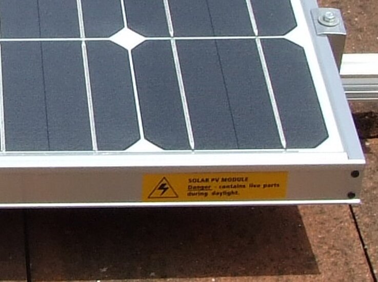
p.s we put warning stickers on EVERY panel saying 'LIVE DURING DAYLIGHT HOURS' - does anyone else?

Not sure as I'd want to put a sign up saying "Isolate before working on the roof" otherwise where would you put it, and how many places would you put it... putting by the isolators is a waste of time, and a big sign on the roof?
 
p.s we put warning stickers on EVERY panel saying 'LIVE DURING DAYLIGHT HOURS' - does anyone else?

Again, we had exactly the same conversation yesterday! My colleague thinks we should be putting these on each VISIBLE side of the panels and a "Do not disconnect under load" sticker. I disagreed as I don't think it is necessary. I think it is fair to say at the very least that anyone messing with the panels would switch off the DC isolator. This removes any load and therefore 99% of the minimal risk when unplugging the panels.
 
Well I think I agree with you Worcester that what you describe would be best practice if you have to bond the array. For a number of reasons I think it is over the top and I also know the DTI guide makes some incorrect statements about PME which lead it down what I believe is an unnecessarily pedantic path. I have only been on this board a couple of months and have a faint recollection that someone here mentioned around the time I joined that the DTI guide was being updated. Anyone know?

One other point about best practice - if you are going to do all the bonds you mention above then they are de facto part of the main protective bonding regime. Therefore every joint must be labelled with a "Safety Electrical Connection - Do Not Remove" label in accordance with 514.13.1.

Regards
Bruce
 
"p.s we put warning stickers on EVERY panel saying 'LIVE DURING DAYLIGHT HOURS' - does anyone else?"

We dont do this - not to say its a bad idea - but anyone working on the PV system should be suitalby qualified and therefore know there "live during daylight", and anyone not; should not be touching with things they dont know about.
 
@BruceB

if you have to bond the array
Agree entirely.
every joint must be labelled with a "Safety Electrical Connection - Do Not Remove"
good point

@dansk, The problem is you get roofers, builders, TV aerial fitters, Sky etc all crawling around there, who may know nothing at all about 'that PV stuff'.

LiveParts-Label.JPG
 

Similar threads

OFFICIAL SPONSORS

Electrical Goods - Electrical Tools - Brand Names Electrician Courses Green Electrical Goods PCB Way Electric Underfloor Heating Electrician Courses Heating 2 Go Electrician Workwear Supplier
These Official Forum Sponsors May Provide Discounts to Regular Forum Members - If you would like to sponsor us then CLICK HERE and post a thread with who you are, and we'll send you some stats etc

Advert

Daily, weekly or monthly email

Thread starter

Email
Joined
Time zone
Last seen

Thread Information

Title
Earthing the Array - Practically
Prefix
N/A
Forum
Solar PV Forum | Solar Panels Forum
Start date
Last reply date
Replies
34

Thread Tags

Advert

Thread statistics

Created
Worcester,
Last reply from
Worcester,
Replies
34
Views
8,225

Advert