Discuss How to shield a live wire at 240V ? in the UK Electrical Forum area at ElectriciansForums.net

Anyway, work in progress and interesting too. ?
I am very angry on this last rock in my way, with the 50hz from the wall. It was hard to make it so far, now is even harder. Imagine how i feel.
From what I understand, my body is like an antena and receives the 50hz from the mains. The 2n7002 transistor is picking up my 50Hz that I receive from the 50hz in the walls. This is the funny part. We must stop receiveing the 50hz from the wall, but allow my 50hz from my body.
My plan is to first pick the signal in the wall, and efectively draw on the wall the position of the wires.
Next is to make a more insensitive SCM (sensing circuit module) than the current one. This one I have with 2n7002 is too sensitive. I plan to make it less sensitive and somehow, balance to not feel the wall fv, but be only sensible to my body. It's an idea and a lot to experiment. But is a way.
I am also thinking on shielding techniques. So far... i have nothing but if I shield the 50hz from the wall, game over, chess mate. I understand your point that it might be the circuit itself a possible solution to the problem, by tweaking it, but I am also after brute force, it never disappoint me.
 
The other practical thing to do is to make the antenna less receptive in some directions and more receptive in other directions. We refer here to the directionality of an antenna. The shape and size of the antenna influences the directionality. You have already been experimenting with an antenna‘s shape and size and there effect on directionality.

Without any discussion right now, we need to design an antenna receptive to the alternating electric field of the mains wiring. If we are clever enough we can make the sensor only receptive and sensitive in a direction along which we want to detect the hand and to be ’electrically deaf’ to the mains electric field being radiated in other directions. A bit like the way the IR photodiode has a cone/fan shaped region of detection.
 
Good idea with the cone of detection. But how?
Another idea I have , is to use another type of circuit that is NOT using 2n7002, is what im trying with these new sensing circuits, with 3 transistors and another fail I made today with an opamp uA741 that doesnt work at all. The idea is to have a secondary sensing circuit (B) only for the 50Hz, somewhere in the left of the board. I want it to not be sensitive to my hand, but only to the 50Hz. My (A) 2n7002 circuit is sensing both my hand and 50hz. On its output to pin5, some sort of module that will compute A-B and output basically only my hand fv to the pin5.
I had to make this AC sensing circuit long time ago. So I am making it now, with double purpose. Is a bit parallel with my main objective but... I have to try it.
I start to have the impression that my hand and the 50hz from the wall is the same thing for the transistor. Only that my signal is not that strong as the one from the wall for him. I was having the impression I have another fv or signal, very different from the one in the wall. But now i realize is probably the same thing, but at different intensities/volume. So in a way, is impossible to separate them only from electronics, and we need to have a very good testing apparatus to find a clear path between all these interference to actually make it do what I want it to do.

I've followed this thread for a few days now, and am very impressed with Marconi's efforts (as always).

But.... can you confirm what the actual requirements are? What are you aiming for?
 
Not really my expertise - just an amateur, but would it not be possible to make a pass through filter or band stop filter designed for 50Hz to sink/block the interference? (one would be wired in parallel the other in series)
Hope I'm not interfering.
Please interfere, we need all the help we can get. Mister @marconi had mentioned something like that a wile ago, but we didnt get to that point yet. He mentioned about low pass filter and peak detector. Now you add something new, pass through filter and band stop filter, I'll have to check what they are and how to use them.
I for one, I dont know this special things how to make and calibrate them. Though I read some articles about them, but still, I cant see the logic to them yet, because lack of experience. I will definitely try it. Thanks for the reminder and for the help.
 
Last edited:
@240V it would be a band pass filter rather than a band stop filter (parallel) Sorry I had assumed 12v or so, I think I need to read the whole thread so ignore me and go with the much more informed Marconi.
@stevethesparks The summary of this circuit is simple. Is working at 5V for all modules, for the entire board circuits. It is working perfectly on the working table. It is messed up on the wall, Near the 240V AC, 50Hz inside the wall. If I put a metal shield in the back of my board, and ground it, again, is working perfectly. BUT if I connect the relay to actually switch the 220, either by inserting the relay in the hole, or by dragging some wires from relay to the live wires in the hole socket, it is terrible messed up, again.
This is the summary.
Mister @marconi here is trying to replicate my circuit with the components he have available and also expecting some from ebay as well. In the same idea of repairing this 50hz interference.
 
Mister @marconi , talking with the guys here I was struck by an idea. I think the relay is so small and cute, that its metal contacts are reverberating through all the minimalist isolation he has in it, and travels on it's (5V) power wires, to the board, to the entire thing, bypassing the grounded metal shield and affecting the sensing circuit. It's like water, getting on a thread to the other side of the board.
Because, as I mentioned it, with the grounded metal shield in the back of the board is working perfectly. BUT if I connect the relay to actually switch the 220, THEN it is messed up. You see it how I see it?
I very much think that the relay should be shielded and filtered and protected to not transmit further the frequency. Right?
 
Here as some simple component additions which may improve the operation of your wings circuitry - see attachment 1. The capacitor C1 - top right red bubble - is to provide some low pass filtering for frequencies above 50Hz. Try C = 0.03uF or thereabouts. At 50Hz its reactance is about 100kOhms so negligible when compared with the 11k (between the 2N2007 source and 0V) across it; at 1000Hz its reactance is 1800 Ohms so lower than the 11k across it. With increasing frequency the 11K will be bypassed.

The other thing you could do which would please me too is physically separate the mains relay from the low voltage circuitry and introduce an optocoupler - something like the circuit I have sketched in my second attachment. The 10uF across the photodiode in the optocoupler is to short out any 50Hz pick up signal appearing between the signal S and 0V. The 500uF does the same for any pick up between 0V and 5V leads to this circuit. Then put the circuit inside a plastic box with the mains going in one end and the low voltage wires into the other rather like what I did with the white oblong connector.

:)
 

Attachments

  • wingsaddcomps.png
    553.2 KB · Views: 11
  • opto.png
    8.9 KB · Views: 11
A very parallel update: Today I am happy I received my first performant oscilloscope. I am waiting for it from my past life. A lot of problems with the mail. But it finally come.
DSO138 is a digital osciloscope
1612184503863.png

I am mentioning here, because mister @marconi asked me what measurement tools I have. So this fall in that category. I have a very old and shitty osciloscope (transistorized) - it is written on it, with the most basic functions imaginable. A friend from another forum encouraged me to take this little thing as a very good upgrade for what I have, and I believe him.
Now that I have it, maybe is a game changer. But the problem is that is a tool I literally dont know how to use it yet. I understand I am not allowed to measure more than 30V with it, if im not mistaken, I have to read more specs about it. So no 220 measuring with it unfortunatly. But for the 5V on my board, it should be very good.
So from now on, consider this tool that I can use.
I also received my IR leds + black photo diodes in 1 package. 50 pairs total = a life time use.
 
I would love and oscilloscope but in reality I cannot justify the expenditure on one. That oscilloscope looks very interesting though- could you send me some details of it please? I think it will be helpful to you in your current and also future projects.

I will keep it brief now and will say more tomorrow morning. My prototype switch will reliably detect flat white sheets of paper presented to the two IR diodes. What I am having problems with is the presentation of the hand to operate the switch reliably. It often does work but the orientation of the hand and which part of my palm‘s skin is illuminated matters greatly. This is is not surprising really because the type of reflection from the smooth white appear is specular and generally consistent whereas when it is off a rough bumpy surface like skin it is diffuse. There is also more absorption of infra red light by skin than by white paper. All quite interesting as a further problem to overcome. My first thought is to use more than one photodiode to look at the illuminated patch of skin from other directions and then combine their signals to determine the presence and closeness of the skin on the palm of the hand. In other words an array of sensors.

Here is a short article on the subject.

Physics Tutorial: Specular vs. Diffuse Reflection - https://www.physicsclassroom.com/class/refln/Lesson-1/Specular-vs-Diffuse-Reflection
 
Last edited:
...That oscilloscope looks very interesting though- could you send me some details of it please? ...
Yes, no problem. I actually did my homework before buying it, looking on mister YouTube for a lot of these litle osciloscopes and then comparing prices on ebay. I spent like several months doing this thing. Ofcourse, not all the time , but sporadically. Then when my friend insisted on it, I already new a lot of them so it was a smooth push for me to give in. I suggest to you to do the same. FOr sure there are many more optiones there that will satisfy your needs. My prerogatives was cheapness. Im not sure if is the same for everybody else. With these in mind, here is my cheap'o osciloscope link:
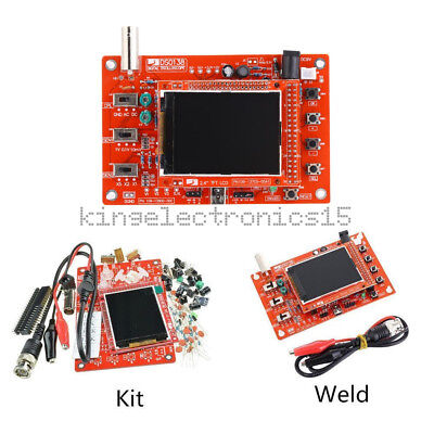
I keep a separate list on my PC for ebay purchase because they are changing with the weather. For example right now their prices changed for the same exact product:
1612209060677.png

Now is 17.88 but my deal was at 16.21. Excelent deal for me.
1612208965753.png

Without plastic case, but im building one from cardboard right now.
If you look lower in the page(scroll down) you will find Product Description, with a lot of information.
You can find at similar price if you search properly. Usually they do that, they change their name both user and product. But if you keep your eyes on the money, you will find it cheap as mine. Be careful not to buy "unsoldered ones". I emailed the guy and I was specifically tell him to send me the soldered one. Because a lot of youtubers were complaining about it, and i learn to avoid it. Youtube is your friend. Use it.
Again, I looked for the cheapest, not the quality. Just enough to do its job.
...My first thought is to use more than one photodiode to look at the illuminated patch of skin from other directions and then combine their signals to determine the presence and closeness of the skin on the palm of the hand. In other words an array of sensors....
Yes, I also suggest a RING of both, sensors and IR leds. I also recomand a high power IR led, like 1W, 3W,5W,10W. If they exist and at what price. I didnt search myself, but I will soon and update you from my side. You should give it a search as well. The ring I have in mind will have around 10x 3mm or 5mm usual leds/sensors. For the power ones, 1 will be enough.
I will update you soon with the circuit that you made for me. I just wake up now and I will start it today.
 

Im not allowed to edit my previeous answer, but I was adding this text next:

In other words an array of sensors.
Check this out ! I was right without even searching for it, but now I searched and I find it:
LED-IR-850nm-940nm-3W-5W-10W-20W-30W-50W-100W-High-Power-Infrared
100W dude! That's what you have to buy ! Hahahaha.
Another link with the cheapest: 1W-3W-Infrared-IR-High-Power-Led
1612213995268.png

Here, 1W or 3W is the same price, so I will choose the 3W if I were you.
1$ for a 3W IR led... it's very good price. It's the cheapest I find.
And you will use the same sensor, BLACK plastic IR photo diode.
 
Last edited:
Good morning. The electronic components I ordered to copy the sensor you have used did not arrive yesterday - maybe today. Today I will play with the make up of my second IR sensor which had the wider field of view photodiode. I mentioned making an array of photodiodes. The thought occurred to me yesterday afternoon while litter-picking ( don't laugh - it is good for the mind and soul!) that I could try one centre IR photodiode and two IR LEDs above and below or left and right or all four in a quad around the photodiode.

In order to combine the signals from each photodiode we will need to construct a summer circuit. I have ordered some 741 operational amplifiers. You may wish to revise your knowledge of summer circuits using op amps:

https://www.electronics-tutorials.ws/opamp/opamp_4.html

One would have to be careful upping the power of the IR radiation because I it will increase not only the desired reflections from the hand but also everything else in the field of view of the sensor which would create a background clutter signal. The most noticeable effect of this would be to illuminate the first or first few LEDs of the the ADVM. This is not something you want to occur in your (or my) final design.

A last thought for something to test on your circuit: could you replace temporarily your 5V power supply with a 6V battery to find out to what extent the power supply is introducing mains interference?
 

Attachments

  • irarray1.png
    8 KB · Views: 4
I have indeed read your posts carefully. They contain good information and creative ideas both of which I have come to expect from you. It is pleasing to see we thinking along similar but not always the very same lines.

:cool:
 
https://www.mouser.co.uk/datasheet/2/427/bpv23nf-1766846.pdf

The idea of using a black photodiode is very clever. I wish I had thought of that but I was not aware of them. Thank you for teaching me something.
Im not that masterful with the IR lights also. But I know how to search.
This is what I bought and the package arrived already yesterday. The black ones are the sensors and the transparent ones are the leds.
1612301514952.png

So my 1W/3W IR led is not such a good idea for you and your tests. You still didnt read all my messages from before. I think this more powerful led will resolve your problems. And also the ring(s) alternative I mentioned. But you do what you can do.
 

Reply to How to shield a live wire at 240V ? in the UK Electrical Forum area at ElectriciansForums.net

Similar Threads

Metal building with living quarters the panel is on the outside and about 20 feet away from new build that will be 2x6 what type of shielded wire...
Replies
3
Views
533
I bought this house a couple months ago. It was built in 1952 (same as me) but has been rewired with yellow 12 awg Romex dated 2007. Looks like a...
Replies
7
Views
513
I want to make some electrical upgrades to my detached garage. I want to update the subpanel in the detached garage, and I want to add a 240V...
Replies
3
Views
718
I removed my baseboard electrical heaters (1981 installed) due to finishing off the room. When I had a new AC ductwork installed they changed the...
Replies
2
Views
399
Hi Everyone, New to the forum but hoping I can find a little help with my restoration project... I am adding a secondary wiring "system" to my...
Replies
14
Views
888

OFFICIAL SPONSORS

Electrical Goods - Electrical Tools - Brand Names Electrician Courses Green Electrical Goods PCB Way Electrical Goods - Electrical Tools - Brand Names Pushfit Wire Connectors Electric Underfloor Heating Electrician Courses
These Official Forum Sponsors May Provide Discounts to Regular Forum Members - If you would like to sponsor us then CLICK HERE and post a thread with who you are, and we'll send you some stats etc

Electrical Forum

Welcome to the Electrical Forum at ElectriciansForums.net. The friendliest electrical forum online. General electrical questions and answers can be found in the electrical forum.
This website was designed, optimised and is hosted by Untold Media. Operating under the name Untold Media since 2001.
Back
Top
AdBlock Detected

We get it, advertisements are annoying!

Sure, ad-blocking software does a great job at blocking ads, but it also blocks useful features of our website. For the best site experience please disable your AdBlocker.

I've Disabled AdBlock