-
Please checkout the new poll we will be pushing hard, and want some good stories to come out of this
result are public - you can change your vote over time, which might genuinely be the case from time to time.
You are using an out of date browser. It may not display this or other websites correctly.
You should upgrade or use an alternative browser.
You should upgrade or use an alternative browser.
Discuss Looks a squeeze, 240 swa thoughts. in the Electricians' Talk area at ElectriciansForums.net

- Reaction score
- 8,188
I have absolutely no experience of cables that big, but if I was asked to do it I might be inclined to do a bit of a switch around, so left cable to right terminals (I'm guessing there is going to be two cables as there are 6 terminals) and vice versa to give myself a bigger bend radius.
Please post up a pick of it when it's done")
Please post up a pick of it when it's done
- Reaction score
- 17,090
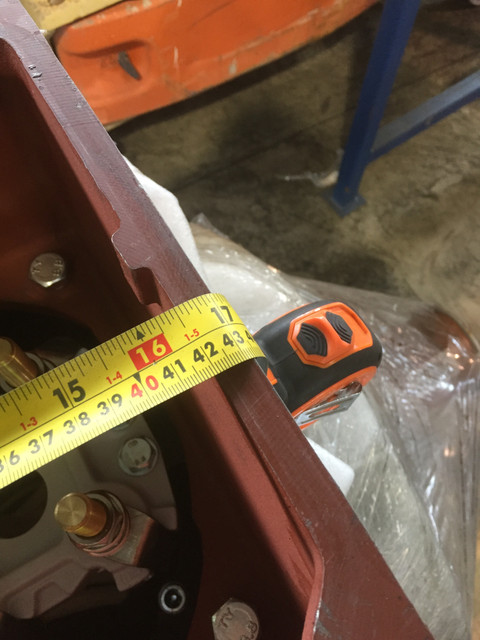
You try, tri rated conductors.Have a 250kW motor with the terminal box in the photo. To me it looks a proper squeeze to bend in the conductors.
Thoughts?
Other options I can think of is allowing the use of SY on this cable only or parallel cables.
- Reaction score
- 17,090
Where did the 240mm2 SWA calcs come from? that's a big old cable. Ignore please I got my sums wrongCannot get them in Pete, ATEX. Have 2 M75 holes so cannot mod the box.
Last edited:
- Reaction score
- 17,090
Yes without eyes on, it was a daft question,Amtech.
FLC is around 420 IIRC. 30+ run on a ladder in a hot factory.
- Reaction score
- 8,188
Am I right in thinking with VFDs that it would be a three core cable, with the motor connected in star formation?
Edit:- I'm thinking it may be dependent on the driver itself.
Edit:- I'm thinking it may be dependent on the driver itself.
- Reaction score
- 17,090
Not sure a motor that size would be started DOLAm I right in thinking with VFDs that it would be a three core cable, with the motor connected in star formation?
Edit:- I'm thinking it may be dependent on the driver itself.
OP
- Reaction score
- 1,173
Am I right in thinking with VFDs that it would be a three core cable, with the motor connected in star formation?
Edit:- I'm thinking it may be dependent on the driver itself.
Yes, a VFD cable should be symmetrically arranged, no 4th core.
1 cable, 3 cores to this motor. 3 if you include the CPC and thyristor cable.
- Reaction score
- 8,188
ThanksYes, a VFD cable should be symmetrically arranged, no 4th core.
1 cable, 3 cores to this motor.
- Reaction score
- 8,188
Not sure a motor that size would be started DOL
I think the VFD would gradually ramp up the frequency and applied voltage over a pre-programmed period of time or at a pre-programmed rate.
I'm trying to learn abit about VFDs as I've got a sneaky feeling one of the farmers I do a bit of work for has one on the feed mill he's wanting to get connected up, so I'm doing a bit of reading around the subject ahead of the inevitable "it don't work chick, can you come and have a look at it for me"
- Reaction score
- 13,475
Perhaps some combination of angled / cranked lugs, so the near one goes straight, the next one is slightly cranked, then the far one kicks up to the lid of the box at 45° and overflies the first two.
If permissible, an additional pre-formed copper link to offset one of the terminals, or even a flag terminal if a suitable one can be found, could allow one core to go on the outside of the studs.
If permissible, an additional pre-formed copper link to offset one of the terminals, or even a flag terminal if a suitable one can be found, could allow one core to go on the outside of the studs.
OP
- Reaction score
- 1,173
Angled lugs! Never seen them, I'll have a google and give the info to the sub-contractor. (they haven't seen this yet)
Pete, its a ATEX motor. No mods whatsoever unfortunately.
I'll also call Rota the manufacturer and see what they say as everyone else must manage somehow.
Pete, its a ATEX motor. No mods whatsoever unfortunately.
I'll also call Rota the manufacturer and see what they say as everyone else must manage somehow.
- Reaction score
- 17,090
Sorry Mate never had any dealings with ATEX why the restrictions on mods?Angled lugs! Never seen them, I'll have a google and give the info to the sub-contractor.
Pete, its a ATEX motor. No mods whatsoever unfortunately.
- Reaction score
- 17,090
Thanks Lee you learn something new every day, I understand the restrictions now, thanks again for the reply.Certified kit pal, it has to be how it was designed to function in hazardous areas.
To be fair this is outside the zone now, but if that changes back I don't my name on a bodged up 10 plus grand motor.
- Reaction score
- 25,532
Two parallel 95.0 ??
- Reaction score
- 25,532
If a 240.0 is adequate 2 x 95.0 should be okay as it should give an improved ccc of 10 to 12%.
- Reaction score
- 10,215
Something doesn't ring right about this thread, firstly we need to know how the motor is going to be started and connected, can we get a pic of the plate here and then go on from there, if we have a star/delta arrangement then the csa of cores can be reduced, from experience they do not make motor connections that are impossible to connect to whether it be space or terminal arrangement, if this seems the case then we have missed something out here.
PS - where did 240mm cable come from?, first mentioned in post 6?
PS - where did 240mm cable come from?, first mentioned in post 6?
B
Bobster
How about 2 x 120mm?
They'll go easy into that.
Edit: most likely be connecting in delta, so it'll fit lovely. An if cable calcs for 1 x 240 is ok, 2 x 120 will be better still.
They'll go easy into that.
Edit: most likely be connecting in delta, so it'll fit lovely. An if cable calcs for 1 x 240 is ok, 2 x 120 will be better still.
- Reaction score
- 25,532
It was a basic calculation based on your 240.0. From Tables 4D4A and 4E4A whereby you half the ccc of the 240.0 and find the nearest csa to that rating which is 95.0, double the ccc of two 95.0s and this is 10 to 12% greater than the single 240.0.
OP
- Reaction score
- 1,173
Something doesn't ring right about this thread, firstly we need to know how the motor is going to be started and connected, can we get a pic of the plate here and then go on from there, if we have a star/delta arrangement then the csa of cores can be reduced, from experience they do not make motor connections that are impossible to connect to whether it be space or terminal arrangement, if this seems the case then we have missed something out here.
PS - where did 240mm cable come from?, first mentioned in post 6?
Hi Darkwood, its a VFD as mentioned a few posts down.
I will dig out the data sheet tomorrow.
Amtech cable calc.
- Reaction score
- 10,215
Of the top of my head I cannot see you needing anything larger than 70mm paralleled up using single core tri-rated, assuming distance not an issue here from VFD to motor if distance is what is causing you to increase CSA then it is that you need to address, there are options of how to do this but also with distance on VFD outputs comes other issues like Harmonics?
How is the final connection to the motor configured is it star or delta?
How is the final connection to the motor configured is it star or delta?
Last edited:
- Reaction score
- 25,532
Too small once you apply grouping factors.Of the top of my head I cannot see you needing anything larger than 70mm paralleled up using single core tri-rated, assuming distance not an issue here from VFD to motor?
- Reaction score
- 10,215
Too small once you apply grouping factors.
Expand on your grouping factor, why would you be applying it here?
- Reaction score
- 223
That's a lump of a motor, is it Ex d or n. Assuming the hazard is dust rather than gases?
- Reaction score
- 25,532
Ccc for tri rated are generally for a single conductor in free space, apply six of them and assuming they will not be separated in free space grouping factors should be applied.Expand on your grouping factor, why would you be applying it here?
- Reaction score
- 10,215
Ccc for tri rated are generally for a single conductor in free space, apply six of them and assuming they will not be separated in free space grouping factors should be applied.
I wasn't trying to trip you up, the cores would generally be grouped into 2 standard recommended tri formation and spaced apart thus minimal grouping factor, the 30m ladder run can account for all the sizing, grouping issues but the final connection only has to be rated for the motor termination, an interim connection unit would be the preferred method and the last link would be in 70mm tri in parallel run in 2 flexi conduits and if delta formation then even better, as each has its own terminal lug, it would of course mean a cable size reduction at the motor but this work falls under machinery control, the VFD protect the cables from overload, the last section (motor link) only needs to be calculated for its limited length and install methods.
Given that the long ladder run is taking the hit for all the grouping etc and is not the final termination to the motor then SWA in parallel is probably a better option there.
PS - just to add as it's running off a VFD it has to be remembered that if tri is used then it still requires a suitable screening method hence the SWA option and flexi metallic conduit to link the motor may be a solution.
Last edited:
- Reaction score
- 25,532
Slight cross wires on my behalf I was considering tri rated for the entire run not just the final connection. Nevertheless the two separate parallel connections would require grouping factors for the three conductors which I calculate to 326.6A.
Rocboni
-
- Reaction score
- 145
I would say SY is the best option here, it offers better screening properties than SWA, not sure if SWA can be classed as 360degree screening? depends if compliance with
89/336/EEC has to be met as defined by the standard EN 61800-3. Cable shield should be grounded at both ends.
Can you not move the inverter next to the inverter and supply with a 240mm SWA?
Ive came across inverters where cable length is limited 30M, but never worked on anything this big!
Would a local isolator be required?
Most likely connected in delta if connected to an inverter.
- Reaction score
- 10,215
I was looking at 105c rated if you get high temp lugs and connection unit then all can be done with reduced sizing, also depending on the motor duty and loading it may not ever need to pull full load and many questions need to be asked but I would find it surprising if we are needing over 70 in parallel if the correct equipment is selected, 95mm parallel may be what is needed but just going by info given.
- Reaction score
- 575
The attached file shows the ways recommended for cabling VSD’s by ABB.
I would not be happy using 105 deg rated cable connected to a motor such as this in a warm environment as the heat from the conductor has to go somewhere and that is usually into the motor which in my experience ends up burning up connections in the motor box.
Also another question to ask is whether the motor is suitable for use with a VSD? Has it been fitted with insulated bearings?
I tend to agree with Rob, 2 x 120mm SWA cables seems to be about right with a seperate earth conductor (not integral).
I do this a lot and regularly install L.V drives on motors up to 550kw in warm environments.
- Reaction score
- 10,215
@Andy 1960
The info from Lee is very limited here,
Motor config'
Onsite options (reduce the VSD distance)
Hot factory??? What exactly do that mean
Speed of motor? Is the motor been speed controlled and if so is additional cooling measures been put in place?
I have already admitted the conditions for 70mm high temp tri would have to be favourable and do rely on a few factors like motor duty and VSD setting, also 70mm 105' degree tri has a unity x1 factor at 45degrees although this could vary dependent on manufacturer ... If the motor has temp' protection and high temp' lugs are used and connected to gear also rated then there should be no issues.
I also do a lot of VSD's although hands up not usually this size but I also do machines that have heating banks, elements etc where temp' is a major headache when choosing suitable cables and connections.
Digging out my cable charts I admit 70mm is a bit optimistic and relies on too many favourables but 95mm with a 0.7 grouping wired in parallel in groups of 2 x 3 formation to the motor from the connection box within metal flexible conduit then any other suitable method of appropriate sizing for install methods between VFD and connection unit wouldn't be so far out of the park here.
http://www.batt.co.uk/upload/files/...ulcsacurrentratingstablebec100_1219731558.pdf
Last edited:
- Reaction score
- 223
Only problem being that the motor is certified and has only 2 x 75mm cables entries.
The last motor of this size that I have worked on was 11kV.
Do you have a picture of the motor information plate?
The last motor of this size that I have worked on was 11kV.
Do you have a picture of the motor information plate?
- Reaction score
- 10,215
To be fair and I have touched on this, I would require a hell of a lot more info of Lee before designer the motor power supply, like I said, even something as simple as having speed control could change the requirements of the existing motor set-up and could require the need for force ventilation.
VSD - Motor cabling also has many factors to be considered here, the BS7671 is based on general cables and their common ratings and values, if you come away from these and go into specialised cabling with different insulation and sheath materials then it can open other options which can see reduction in CSA, I use IGUS and LAPP brands which can mean you have to forget the BS7671 charts and use the manufacturers guides.
VSD - Motor cabling also has many factors to be considered here, the BS7671 is based on general cables and their common ratings and values, if you come away from these and go into specialised cabling with different insulation and sheath materials then it can open other options which can see reduction in CSA, I use IGUS and LAPP brands which can mean you have to forget the BS7671 charts and use the manufacturers guides.
- Reaction score
- 575
Darkwood, I agree the info is a bit sketchy and I have not had much to do with ATEX installations. It’s a very onerous minefield in my opinion!
One thing I do recall though is that I believe the VSD and the motor have to be a matched pair in order to comply with the regs.
Something else the OP should maybe look into as well as the requirement for insulated bearings that I mentioned in my earlier post.
One thing I do recall though is that I believe the VSD and the motor have to be a matched pair in order to comply with the regs.
Something else the OP should maybe look into as well as the requirement for insulated bearings that I mentioned in my earlier post.
- Reaction score
- 10,215
@Andy-1960
You and me both - ATEX is not my field either so will leave comment on that side for others, I am interested in your matched comment, do you mean brand matched or motor is actually matched to the drive on a individual basis.. given the tech' now in VSD's I am somewhat confused by the matched comment?
As for insulated bearings, I was led to believe most modern VSD friendly motors were designed to limit/stop circulating currents through the bearings, agree if it is deemed to be an issue with this setup then it does want addressing.
- Reaction score
- 25,532
I would assume matched to the motor and not by brand.
- Reaction score
- 10,215
I ask because their is a certain brand out there that match their motors to their VSD's, I believe they program up the drives to account for certain anomalies in the frequency blind spots due to the design of the motor.. I have seen one of their motors run on another brand VSD and it just trips out and the motor gives some very strange HF noises out.
Modern VFD's can be taught or self teach about the motor connected, I just wondered why the matching ?.. unless it just means been pre-programmed up at factory as it can get complicated when using Vector, small errors in settings can have running issues.
Modern VFD's can be taught or self teach about the motor connected, I just wondered why the matching ?.. unless it just means been pre-programmed up at factory as it can get complicated when using Vector, small errors in settings can have running issues.
- Reaction score
- 575
It was a project I was involved with a little while back. It involved extract fans within a refrigeration plant room. The refrigerant was ammonia so it was deemed to be an ATEX zone where the fan was sited, but the VSD was in the safe area. The consultant on the project said that the VSD and the motor had to be a matched pair if the VSD was running the motor during a leak. The work around was to by pass the VSD and run the fan at full speed from the mains when a leak was detected. Not sure of the reasoning behind the matched pairing, but it was definitely to do with the ATEX certification for the project. I will try and do a little more digging.
- Reaction score
- 649
Interesting to see how this pans out,does seem nearly impossible to connect that sized Swa into that box.
Help from motor company may be advisable,the last one I did we did 2 cables in parallel,thinking that was 2x35mm,easy .
The last time we installed 240mm x2 was for a recycling plant,terminating into main panel,that was hard work,but had enough room to make a decent connection.
Help from motor company may be advisable,the last one I did we did 2 cables in parallel,thinking that was 2x35mm,easy .
The last time we installed 240mm x2 was for a recycling plant,terminating into main panel,that was hard work,but had enough room to make a decent connection.
OP
- Reaction score
- 1,173
Wow, info overload...I’ll do my best to cover everybody’s input.
Motor 262kW 461A. It will run to its FLC, the smaller 30kW machine does so that has to be presumed so.
SY is no more an more ideal cable than SWA, the cores are not symmetrical and often the braid is terrible.
SWA is not ideal but symmetry is possible and is generally accepted as being sufficient. Especially when the ELV control is also SWA. The most important factor is the low impedance back to the chassis of the vsd from the motor which will be achieved on all the drives on the project by bonding from the motor frame to the containment as well as the supply armour, the thermistor armour and the cpc.
I know the most ideal cables are the foil wrapped with the 3 symmetrical cpc’s but I cannot run those types of cables in this environment on 900mm ladder.
Inverter location is fixed, I think I can get the route just below 30m.
Hot factory?? Ambient temp correction factor. 40 degC
I don’t see how I can use tri rated for a few reasons, EMC compliance, getting them in 2 M75 holes....
Darkwood, of the motor is pulling its FLC, and I do not have the knowledge to de rate the cables just through experience on something this large.
Forced ventilation is not required, the smaller ones runs 40~60Htz.
x2 120’s seems possible.
Thanks to all who have contributed so far.
Last edited:
Reply to Looks a squeeze, 240 swa thoughts. in the Electricians' Talk area at ElectriciansForums.net
Similar Threads
Hi. Im looking for some advice when calculating submain cables.
Basically there is a new connection of 80Amps that is to be used for a dwelling...
- Replies
- 5
- Views
- 415
Hi Guys
After bit of advice please as we don't do much data normally, tend to sub it out.
Had garden building this week which we'd run in SWA...
- Replies
- 9
- Views
- 438
Hi All,
I'm new to Amtech/Trimble and I've been asked to review a model.
I'm looking at circuits that are SWA cables using the armour and an...
- Replies
- 4
- Views
- 616
I have a question which is confusing me and I cannot find a definitive answer and I hope someone can help.
So I have a PC and Monitor and I have...
- Replies
- 4
- Views
- 486
TNC-S main supply with 16mm swa supplying garage consumer unit from main consumer unit in house, then 4mm swa supplying pond equipment through...
- Replies
- 36
- Views
- 3K
OFFICIAL SPONSORS


These Official Forum Sponsors May Provide Discounts to Regular Forum Members - If you would like to sponsor us then CLICK HERE and post a thread with who you are, and we'll send you some stats etc
YOUR Unread Posts
-
 External Consumer UnitThere are also stainless steel options in that range and not too expensive (comparatively).
- Latest: nicebutdim
-
 Best certification softwarehttp://www.tysoft.co.uk/easycert.htm I have used this software for years and find it excellent...
- Latest: SparkySy
-
 Dodgy trade pictures for your amusement! - 1 Million Views!Looks a bit flip floppy to me.... are they cooking sole(s) on a griddle?
- Latest: ipf
This website was designed, optimised and is hosted by untold.media Operating under the name Untold Media since 2001.